USER’S MANUAL M1740009.
LIMITED WARRANTY A. Warranty - LEESON Electric warrants that its products will be free from defects in material and workmanship for a period of one (1) year from the date of shipment thereof. Within the warranty period, LEESON will repair or replace such products that are returned to LEESON or to the nearest Branch Office, with shipping charges prepaid. At our option, all return shipments are F.O.B. LEESON or its Branch Office.
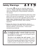
i Safety Warnings • This symbol denotes an important safety tip or SHOCK HAZARD AVOID HEAT KEE DR OID ATION warning. Please read these instructions carefully before performing any of the procedures contained in this manual. • Have a qualified electrical maintenance technician install, adjust, and service this equipment.
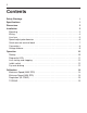
ii Contents Safety Warnings i Specifications 1 Dimensions 2 Installation 3 Mounting . . . . . . . . . . . . . . . . . . . . . . . . . . . . . . . . . . . . . . . . . . . . . . . . . . . . .3 Wiring . . . . . . . . . . . . . . . . . . . . . . . . . . . . . . . . . . . . . . . . . . . . . . . . . . . . . . .4 Line fuse . . . . . . . . . . . . . . . . . . . . . . . . . . . . . . . . . . . . . . . . . . . . . . . . . . . . .5 Speed adjust potentiometer . . . . . . . . . . . . . . . . . . . . . . . . . .
Contents iii Application Notes 17 Multiple fixed speeds . . . . . . . . . . . . . . . . . . . . . . . . . . . . . . . . . . . . . . . . . . .17 Adjustable speeds using potentiometers in series . . . . . . . . . . . . . . . . . . . . .18 Independent adjustable speeds . . . . . . . . . . . . . . . . . . . . . . . . . . . . . . . . . . .19 RUN/JOG Switch . . . . . . . . . . . . . . . . . . . . . . . . . . . . . . . . . . . . . . . . . . . . . .20 Reversing . . . . . . . . . . . . . . . . . . . . . . . . . .
iv Illustrations Figure Figure Figure Figure Figure Figure Figure Figure Figure Figure Figure Figure Figure Figure Figure Figure Figure 1. M1740009.00 Dimensions . . . . . . . . . . . . . . . . . . . . . . . . . . . . . . . . . . . . . . . . . . . . .2 2. Fuseholder . . . . . . . . . . . . . . . . . . . . . . . . . . . . . . . . . . . . . . . . . . . . . . . . . . . . . . . .5 3. Speed Adjust Potentiometer . . . . . . . . . . . . . . . . . . . . . . . . . . . . . . . . . . . . . . . . . . .6 4.
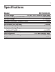
1 Specifications Model M1740009.00 AC Line Voltage 115 VAC, ±10%, 50/60 Hz, single phase Horsepower Range (with 130 VDC motors) 1/20 - 1/3 HP Armature Voltage 0 - 130 VDC Maximum Continuous Armature Current 2 ADC Form Factor (at base speed) 1.
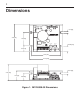
2 Dimensions BR501 D501 Q501 A G S TH501 K 0.19 [5] C502 3.58 [91] 1.75 [44] FU501 R502 C501 R503 MAX SPD P501 R501 0.65 [16] TORQUE P502 SO501 P503 0.74 [19] IL501 PWR IL502 CUR LIM P504 NEG NEG MIN SPD IR COMP 3.80 [97] 4.30 [109] 0.19 [5] 2.15 [55] 1.28 [33] 0.97 [25] Figure 1. M1740009.
3 Installation Mounting • Protect the drive from dirt, moisture, and accidental contact. • Provide sufficient room for access to the terminal block and calibration trimpots. • Mount the drive away from heat sources. Operate the drive within the specified ambient operating temperature range. • Prevent loose connections by avoiding excessive vibration of the drive. • Mount drive with its board in either a horizontal or vertical plane. Six 0.19 in.
4 Installation Wiring • Use 18 AWG wire for speed adjust potentiometer wiring. Use 16 AWG wire for motor and AC line voltage wiring. • Twist logic wires (for speed adjust potentiometer and inhibit) to avoid picking up unwanted elertrical noise. Use shielded cable if wires are longer than 18 in. (46 cm). • Keep logic wires away from power carrying lines or sources of electrical noise that can cause erratic operation.
Installation 5 Line fuse The M1740009.00 drive is protected by a 5A, 250V AC line fuse. The fuse does not have to be resized as long as the motor used is within the drive’s specified horsepower range. The fuse is mounted in the fuseholder (see Figure 2). To replace a blown fuse, use a screwdriver to turn the fuseholder knob counterclockwise. Remove the blown fuse and replace with a new fuse. FUSE HOLDER KNOB Figure 2.
6 Installation Speed adjust potentiometer Mount the speed adjust potentiometer through a 0.38 in. (10 mm) hole with the hardware provided (see Figure 3). Install the circular insulating disk between the panel and the 10K ohm speed adjust potentiometer. Twist the speed adjust potentiometer wire to avoid picking up unwanted electrical noise. If the potentiometer leads are longer than 18 in. (457 mm), use shielded cable (see Wiring section).
Installation 7 Quick-connect terminal block The quick-connect terminal block has an 8-pin header block and 8-screw terminal plug (Figure 4). To use the quickconnect terminal block: 1. Carefully pull the terminal plug from the header block. 2. With a small flat-head screwdriver, turn the terminal plug screw counterclockwise to open the wire clamp. 3. Insert a stripped wire into the large opening in front of the plug. 4. Turn the terminal plug screw clockwise to clamp the wire. 5.
8 Installation Connections L1 L2 A1 A2 S3 S2 H2 S1 CW 10K SPD ADJ POT LINE VOLTAGE 115 VAC H1 RUN STOP INHIBIT SWITCH (optional) MOTOR Figure 5. Drive Connections Assumptions: This drive series supplies motor voltage from its A1 and A2 terminals. It is assumed throughout this manual that when A1 is positive with respect to A2, the motor will rotate clockwise (CW) while looking at the output shaft protuding from the front of the motor.
Installation 9 Voltage follower Instead of using a speed adjust potentiometer, the drive may be wired to follow a 0 - 5 VDC voltage signal that is isolated from earth ground (Figure 6). Connect the signal input (+) to S2. Connect the signal common (-) to S1. Make no connection to S3. A potentiometer can be used to scale the analog input voltage. L1 L2 A1 A2 S3 S2 H2 S1 + - H1 0 - 5 VDC ISOLATED VOLTAGE SIGNAL INPUT Figure 6.
10 Operation Startup Note: Before applying power, verify that no conductive material is placed on the printed circuit board. To start the drive: 1. Turn the speed adjust potentiometer full counterclockwise (CCW). If the drive is following a voltage signal, set the voltage signal to 0 VDC. 2. Apply power. 3. Slowly advance the speed adjust potentiometer clockwise (CW). If the drive is following a voltage signal, slowly increase the voltage signal.
Operation Diagnostic LEDs This drive is equipped with two diagnostic LEDs: power status (PWR) and current limit mode (CUR LIM). See Figure 7 for LED locations. POWER (PWR): Green LED lights whenever AC line voltage is applied to the drive. CURRENT LIMIT (CUR LIM): Red LED lights whenever the drive reaches current limit. POWER LED Figure 7.
12 Operation Line starting and stopping Line starting and stopping (applying and removing AC line voltage) is recommended for infrequent starting and stopping of a drive only. When AC line voltage is applied to the drive, the motor accelerates to the speed set by the speed adjust potentiometer. When AC line voltage is removed, the motor coasts to a stop. Inhibit switch An inhibit switch allows the motor to decelerate to zero speed when the switch is closed.
Operation 13 INHIBIT SWITCH (optional) STOP RUN Figure 8. Inhibit Switch A2 MOTOR RUN A1 H2 H1 BRAKE 1 OHM 1 W BRAKE RESISTOR A 1 Ohm, 1 W resistor is used as the dynamic brake resistor. For motors rated 1/17 horsepower and lower, a dynamic brake resistor is not necessary since the armature resistance is high enough to stop the motor without demagnetization. In this case, replace the dynamic brake resistor with 12 gauge wire. Figure 9.
14 Calibration Each drive is factory calibrated to its maximum current rating. Re-adjust the calibration trimpot settings to accomodate lower current motors. All adjustments increase with CW rotation, and decrease with CCW rotation. Use a non-metallic screwdriver for calibration. Each trimpot is identified on the printed circuit board. Minimum Speed (MIN SPD) The MIN SPD setting determines the motor speed when the speed adjust potentiometer is turned full CCW. It is factory set for zero speed.
Calibration 15 Regulation (IR COMP) The IR COMP setting determines the degree to which motor speed is held constant as the motor load changes. It is factory calibrated for a 1/8 HP, 90 VDC motor. Recalibrate the IR COMP setting when using a lower current motor. Refer to the recommended IR COMP settings in Figure 10, or recalibrate using the following procedure: If the motor does not maintain set speed as the load changes, gradually rotate the IR COMP trimpot CW.
16 Calibration TORQUE (cont.) 3. Lock the motor armature. Be sure that the motor is firmly mounted. 4. Connect power to the drive. The motor should remain stopped. 5. Set the speed adjust potentiometer to maximum (full CW). 6. Adjust the TORQUE trimpot CW slowly until the armature current is 120% of motor rated armature current. 7. Set the speed adjust potentiometer to minimum and remove power from the drive. 8. Remove the stall from the motor. TORQUE TORQUE TORQUE IR COMP 1/4 HP 130 VDC 2500 RPM 1.
17 Application Notes Multiple fixed speeds Replace the speed adjust potentiometer with series resistors with a total series resistance of 10K ohms (Figure 11). Add a single pole, multi-position switch with the correct number of positions for the desired number of fixed speeds. R1 S3 R2 S2 R3 S1 TOTAL SERIES RESISTANCE 10K OHMS R4 Figure 11.
18 Application Notes Adjustable speeds using potentiometers in series Replace the speed adjust potentiometer with a single pole, multi-position switch, and two or more potentiometers in series, with a total series resistance of 10K ohms. Figure 12 shows a connection for fixed high and low speed adjust potentiometers. CW S3 HIGH SPEED 5K OHM LOW SPEED CW S2 S1 5K OHM Figure 12.
Application Notes 19 Independent adjustable speeds Replace the speed adjust potentiometer with a single pole, multi-position switch, and two or more potentiometers in parallel, with a total parallel resistance of 10K ohms. Figure 13 shows the connection of two independent speed adjust potentiometers that can be mounted at two separate operating stations. S3 SPEED 2 CW CW SPEED 1 20K OHM 20K OHM S2 S1 Figure 13.
20 Application Notes RUN/JOG S witch Using a RUN/JOG switch is recommended in applications where quick stopping is not needed and frequent jogging is required. Use a single pole, single throw switch for the RUN/JOG switch, and a single pole, normally closed, momentary operated pushbutton for the JOG pushbutton (see Figure 14). When the RUN/JOG switch is set to JOG, the motor decelerates to zero speed. Press the JOG pushbutton to jog the motor. Return the RUN/JOG switch to RUN for normal operation.
Application Notes 21 Reversing A dynamic brake may be used when reversing the motor direction (Figure 15). Use a three pole, three position switch rated for at least the maximum DC armature voltage and maximum braking current. Wait for the motor to stop completely before switching it to either the forward or reverse direction. A2 FORWARD BRAKE REVERSE MOTOR 1 Ohm 1 W Dynamic Brake Resistor A1 H2 H1 Figure 15.
22 Troubleshooting Warning Dangerous voltages exist on the drive when it is powered. When possible, disconnect the AC line voltage from the drive while troubleshooting. Be alert. High voltages can cause serious or fatal injury. Before troubleshooting Perform the following steps before starting any procedure in this section: 1. Disconnect AC line voltage from the drive. 2. Check the drive closely for damaged components. 3.
Troubleshooting 23 Motor does not run 1. Check for blown fuses or tripped circuit breaker. 2. Verify that the speed adjust potentiometer is not set to zero speed position. 3. Verify that the inhibit terminals (H1 and H2) are not shorted together. 4. Verify that the drive is receiving AC line voltage. 5. Check that the drive is not in current limit. The red current limit (CUR LIM) LED must be off. If the red current limit LED is on, verify that the motor is not jammed.
24 Troubleshooting Motor will not stop when the speed adjust potentiometer is full counterclockwise 1. Turn the MIN SPD trimpot CCW until the motor stops. Motor runs in the opposite direction 1. Remove AC line voltage. 2. Reverse connections to the motor armature. Motor slows under load 1. Check that the drive has been correctly calibrated for the motor. 2. Check that the motor is not overloaded. 3. Re-adjust the IR COMP slightly CW until the motor runs at proper speed. Motor is unstable under load 1.
25 Block Diagrams S3 (H1) S2 MAX/MIN SPEED CIRCUIT S1 (H2) PWM CIRCUIT +VBUS IR COMP CIRCUIT POWER BRIDGE CIRCUIT L1 L2 FU501 CURRENT LIMIT CIRCUIT Figure 16.
L2 L1 FU501 5A / 3AG MOV1 S1 (H2) S2 S3 (H1) 33K D1 15V .5W P501 100K R14 33K MIN SPD CW MAX SPD 3 TH501 R9 15K R13 300K P503 10K C3 1/35 CW R15 330K 3 +5V C4 R502 6.8K/10W + - R16 330K 5 6 Figure 17.
27 NOTES
28 NOTES
29 NOTES
DISCLAIMER The information and technical data in this manual are subject to change without notice. LEESON Electric makes no warranty of any kind with regard to this material, including, but not limited to, the implied warranties of merchantability and fitness for a particular purpose. LEESON Electric assumes no responsibility for any errors that may appear in this manual and makes no commitment to update or to keep current the information in this manual. 2100 Washington Street Grafton, WI 53024-0241, U.S.