SPEEDMASTER™ SCR THYRISTOR MOTOR CONTROLS Catalog Numbers 174100, 174105, 174307, 174308, 174311, 174709, M1740005, M1740006, M1740007 OPERATION MANUAL
LIMITED WARRANTY A. Warranty - Leeson Electric Corporation (referred to as “the Corporation”) warrants that its products will be free from defects in material and workmanship for a period of one (1) year from the date of shipment thereof. Within the warranty period, the Corporation will repair or replace such products that are returned to Leeson Electric Corporation or to the nearest Branch Office, with shipping charges prepaid. At our option, all return shipments are F.O.B.
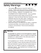
i SPEEDMASTER™ OPERATION MANUAL Safety Warnings • This symbol denotes an important safety tip or SHOCK HAZARD • • AVOID HEAT KEE DR OID ATION warning. Please read these instructions carefully before performing any of the procedures contained in this manual. DO NOT INSTALL, REMOVE, OR REWIRE THIS EQUIPMENT WITH POWER APPLIED. Have a qualified electrical technician install, adjust and service this equipment.
ii SPEEDMASTER™ OPERATION MANUAL Contents Specifications 1 Dimensions 3 Installation 10 Chassis (uncased) drive installation . . . . . . . . . . . . . . . . . . . . . . . . . . .10 Mounting . . . . . . . . . . . . . . . . . . . . . . . . . . . . . . . . . . . . . . . . . . . . .10 Wiring . . . . . . . . . . . . . . . . . . . . . . . . . . . . . . . . . . . . . . . . . . . . . . . .11 Shielding guidelines . . . . . . . . . . . . . . . . . . . . . . . . . . . . . . . . . . .12 Heat sinking . . . . . . .
SPEEDMASTER™ OPERATION MANUAL Contents All drives . . . . . . . . . . . . . . . . . . . . . . . . . . . . . . . . . . . . . . . . . . . . .29 Meter header block (174311 and M174007.OO drives only) . . . . . . . . .29 Starting and Stopping Methods . . . . . . . . . . . . . . . . . . . . . . . . . . . . . . .30 Line starting and line stopping . . . . . . . . . . . . . . . . . . . . . . . . . . . . .30 Inhibit circuit . . . . . . . . . . . . . . . . . . . . . . . . . . . . . . . . . . . . . . . . . . .
iv SPEEDMASTER™ OPERATION MANUAL Illustrations Figure Figure Figure Figure Figure Figure Figure Figure Figure Figure Figure Figure Figure Figure Figure Figure Figure Figure Figure Figure 1. 2. 3. 4. 5. 6. 7. 8. 9. 10. 11. 12. 13. 14. 15. 16. 17. 18. 19. 20. Figure Figure Figure Figure Figure Figure Figure 21. 22. 23. 24. 25. 26. 27. 174311 and M1740007 Dimensions . . . . . . . . . . . . . . . . . . . . . .3 174307 and M1740005 Dimensions . . . . . . . . . . . . . . . . . . . . . .
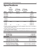
1 SPEEDMASTER™ OPERATION MANUAL Specifications Model M1740007 Max. Armature Current (Amps DC) HP Range with 115 VAC Applied 1.5 1/20–1/8 HP Range with 230 VAC Applied Style Chassis M1740005 NEMA 1 M1740006 NEMA 4X 174311 † 5.0 1/8–1/2 1/4–1 174307 ‡ 174308 ‡ 174100 NEMA 1 10.0 1/8–1 1/4–2 NEMA 4X 15 1 – 1.5 2–3 NEMA 4X 174105 174709 Chassis NEMA 1 NEMA 4X † Double maximum armature current and horsepower when drive is mounted on heat sink part number 174314.
2 SPEEDMASTER™ OPERATION MANUAL Analog Input Voltage Range (signal must be isolated; S1 to S2) 0–90 VDC Armature Voltage 0–1.4 VDC 0–180 VDC Armature Voltage 0–2.8 VDC Input Impedance (S1 to S2) 100K ohms Load Regulation Vibration Safety Certification Ambient Temp. Range chassis drive cased drive 1% base speed or better 0.5G max (0–50 Hz) 0.
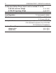
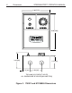
3 SPEEDMASTER™ OPERATION MANUAL Dimensions 0.19 [5] 1.60 [41] 1.28 [33] SCR501 D502 D501 A2 MOV502 0.96 [24] SCR502 D503 0.19 [5] R501 R502 MO F2 V501 F1 C503 L1 1 C501 MOV503 L2 3.58 [91] - IC502 T501 SW501 A1 1.75 [44] 115 230 SO502 + METER S2 C502 IC501 C504 + SO501 S3 INHIBIT SPEEDMASTER 90 180 SW502 CL IL501 TORQUE IR COMP S1 0.74 [19] 0.64 [16] ACCEL DECEL MAX SPD MIN SPD 3.80 [97] 4.30 [109] ALL DIMENSIONS IN INCHES [MILLIMETERS] Figure 1.
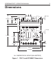
4 Dimensions SPEEDMASTER™ OPERATION MANUAL 6.00 [152] 8.00 [203] 3.46 [88] 2.75 [70] 1.72 [44] 2.50 [64] TWO 0.88 [22] CONDUIT HOLES ALL DIMENSIONS IN INCHES [MILLIMETERS] Figure 2.
SPEEDMASTER™ OPERATION MANUAL Dimensions 6.00 [152] 40 50 RUN 60 30 70 10 90 20 80 0 100 BRAKE FORWARD SPEED WARNING! POWER ALLOW MOTOR TO STOP BEFORE REVERSING 3.46 [88] REVERSE 8.00 [203] 2.75 [70] 1.72 [44] 2.50 [64] TWO 0.88 [22] CONDUIT HOLES ALL DIMENSIONS IN INCHES [MILLIMETERS] Figure 3.
6 Dimensions SPEEDMASTER™ OPERATION MANUAL 6.90 [175] 6.30 [160] 7.78 [198] 8.20 [208] 6.00 [152] 0.19 [5] 4.50 [1 14] 3.70 [94] 0.13 [3] 2.25 [57] 2.50 [64] TWO 0.88 [22] KNOCKOUTS ALL DIMENSIONS IN INCHES [MILLIMETERS] Figure 4.
SPEEDMASTER™ OPERATION MANUAL Dimensions 6.90 [175] 6.30 [160] 1.37 [35] 10.20 [259] 9.76 [248] 7.00 [178] 0.19 [5] 5.49 [139] 4.78 [121] 0.13 [3] 2.37 [60] 2.50 [64] TWO 0.88 [22] KNOCKOUTS ALL DIMENSIONS IN INCHES [MILLIMETERS] Figure 5.
8 Dimensions SPEEDMASTER™ OPERATION MANUAL 6.90 [175] 6.30 [160] POWER 1.39 [35] SPEED 7.00 [178] 10.20 [259] 9.78 [248] 0.19 [5] 0.30 [8] THREE 0.88 [11] KNOCKOUTS ON 1.50 [38] CENTERS 5.50 [140] 4.74 [120] 0.13 [3] 2.40 [60] ALL DIMENSIONS IN INCHES [MILLIMETERS] Figure 6.
SPEEDMASTER™ OPERATION MANUAL 9 Dimensions 6.90 [175] 6.30 [160] 5.90 [150] A C B MOUNTING SLOTS 0.19 X .34 [5 X 9] 0.13 [3] PART NO. DIM “A” DIM “B” 174314 4.40 [112] 3.00 [76] 174316 7.78 [198] 6.00 [152] Heat sinks sold separately. DIM “C” 0.7 [18] 0.89 [23] ALL DIMENSIONS IN INCHES [MILLIMETERS] Figure 7. Heat Sink Dimensions 1.
10 SPEEDMASTER™ OPERATION MANUAL Installation Chassis (uncased) drive installation Mounting • • • • • • • Drive components are sensitive to electrostatic fields. Avoid contact with the circuit board directly. Hold drive by the chassis only. Protect the drive from dirt, moisture, and accidental contact. Provide sufficient room for access to the terminal block and calibration trimpots. Mount the drive away from other heat sources.
SPEEDMASTER™ OPERATION MANUAL Installation 11 Wiring Warning Ꮨ Do not install, remove, or rewire this equipment with power applied. Failure to heed this warning may result in fire, explosion, or serious injury. Circuit potentials are at 115 VAC or 230 VAC above ground. To prevent the risk of injury or fatality, avoid direct contact with the printed circuit board or with circuit elements. Do not disconnect any of the motor leads from the drive unless power is removed or the drive is disabled.
12 Installation SPEEDMASTER™ OPERATION MANUAL Shielding guidelines Warning Under no circumstances should power and logic leads be bundled together. Induced voltage can cause unpredictable behavior in any electronic device, including motor controls. As a general rule, Leeson recommends shielding of all conductors. If it is not practical to shield power conductors, Leeson recommends shielding all logic-level leads.
SPEEDMASTER™ OPERATION MANUAL Installation 13 Heat sinking Model 174311 requires an additional heat sink when the continuous armature current is above 5 ADC. Use Leeson part number 174314. Use a thermally conductive heat sink compound between the drive chassis and heat sink surface for optimum heat transfer. No additional heat sinking is required for Model M1740007. Line fusing The National Electric Code requires the installation of a circuit breaker or fuse on the incoming AC line voltage.
14 Installation SPEEDMASTER™ OPERATION MANUAL Table 1.
SPEEDMASTER™ OPERATION MANUAL Installation 15 Speed adjust potentiometer Warning Be sure that the potentiometer tabs do not make contact with the potentiometer enclosure. Grounding the input will cause damage to the drive. On chassis drives, install the circular insulating disk between the panel and the 10K ohm speed adjust potentiometer. Mount the speed adjust potentiometer through a 0.38 in. (10 mm) hole with the hardware provided (Figure 8).
16 Installation SPEEDMASTER™ OPERATION MANUAL Connections Warning Do not connect this equipment with power applied. Failure to heed this directive may result in fire or serious injury. Leeson strongly recommends the installation of a master power switch in the voltage input line, as shown in Figure 9 (page 18). The switch contacts should be rated at a minimum of 200% of motor nameplate current and 250 volts.
SPEEDMASTER™ OPERATION MANUAL Installation 17 Power input Connect the AC line power leads to PCB terminals L1 and L2, or to a double-throw, single-pole master power switch (recommended). The switch should be rated at a minimum of 250 volts and 200% of motor current. Line fuse Wire an external line fuse between the stop switch (if installed) and the L1 terminal on the PCB. An additional line fuse should be installed on L2 if the input voltage is 230VAC.
SPEEDMASTER™ OPERATION MANUAL A2 1 MOV503 C501 SW501 L2 IC502 T501 - LINE FUSE SCR502 MOTOR R502 F2 F1 + A1 L2 FUSE (see notes) A2 MO V5 01 L1 D503 D502 D501 L1 C503 SCR501 R501 Installation MOV502 18 11 5 230 SO502 + METER S2 C502 A1 IC501 C504 S2 + SO501 S3 INHIBIT 90 S1 SPEEDMASTER 180 SW502 CL IL501 S1 S3 STOP SWITCH ACCEL DECEL MAX SPD MIN SPD TORQUE IR COMP CW 115/230 VAC LINE VOLTAGE 10K OHMS SPEED ADJUST POTENTIOMETER NOTE: DO NOT ADD LINE FUSE
SPEEDMASTER™ OPERATION MANUAL Installation 19 Voltage follower Instead of using a speed adjust potentiometer, the drive may be wired to follow a voltage signal that is isolated from earth ground (Figure 10). Connect the signal input (+) to S2. Connect the signal common (–) to S1. Make no connection to S3. A potentiometer can be used to scale the analog input voltage. For 90 VDC motors, the voltage range is 0 - 1.4 VDC. For 180 VDC motors, the voltage range is 0 - 2.8 VDC.
20 Installation SPEEDMASTER™ OPERATION MANUAL Cased drive installation Mounting (NEMA 1 enclosures) NEMA 1 cased drives come with 0.88 inch (22 mm) conduit holes at the bottom of the case. The units may be vertically wall mounted or horizontally bench mounted using the three keyholes on the back of the case (see Figure 11). To mount the drive: 1. 2. 3. 4. 5. 6. For access to the keyholes and the terminal strip, remove the two screws from the front of the case by turning them counterclockwise.
SPEEDMASTER™ OPERATION MANUAL Installation 21 6.00 [152] CL 1.79 [45.0] 2.50 [64] 2.50 [64] 8.00 [203] 5.00 [127] Figure 11. NEMA 1 Mounting Hole Locations Mounting (NEMA 4 and NEMA 4/12 enclosures) NEMA 4/12 cased drives (models 174100 and 174105) come with two 0.88 inch (22 mm) conduit knockout holes at the bottom of the case. Model 174709, a NEMA 4 cased drive, comes with three knockout holes at the bottom of the case.
22 Installation SPEEDMASTER™ OPERATION MANUAL To mount the drive: 1. 2. 3. 4. 5. 6. 7. Install the mounting screws. For access to the terminal strip, turn the slotted screw on the front cover counterclockwise until it is free from the case. The right side of the cover is hinged to the case. Pull the slotted screw to open the case. Carefully remove the conduit knockouts by tapping them into the case and twisting them off with pliers. Install conduit hardware through the 0.
SPEEDMASTER™ OPERATION MANUAL Installation 23 Line fusing Line fuses are preinstalled on all cased drives. Models 174307, 174308, 174100, and 174105 have 15A line fuses; model 174709 has 30A line fuses; and models M1740005 and M1740006 have 3A line fuses. If the horsepower rating of the motor being used is less than the maximum horsepower rating of the drive, the line fuse may have to be replaced with a lower rated one. Refer to Table 1 on page 14 for recommended line fuse sizes.
24 Installation SPEEDMASTER™ OPERATION MANUAL 1 2 3 4 5 EARTH GROUND (GREEN SCREW) 115 VAC 230 VAC 115 OR 230 VAC LINE VOLTAGE INPUTS MOTOR ARMATURE Figure 12. Cased Drive Connections A1 A2 EARTH GROUND (GREEN SCREW) 115 VAC 230 VAC 115 OR 230 VAC LINE VOLTAGE INPUTS Figure 13.
25 SPEEDMASTER™ OPERATION MANUAL Operation Warning Change voltage switch settings only when the drive is disconnected from AC line voltage. Make sure both switches are set to their correct position. If the switches are improperly set to a lower voltage position, the motor will not run at full voltage. If the switches are improperly set to a higher voltage position, the motor will overspeed, which may cause motor damage.
26 Operation SPEEDMASTER™ OPERATION MANUAL Startup 174311 and M1740007 1. 2. 3. 4. Turn the speed adjust potentiometer full counterclockwise (CCW). Apply AC line voltage. Slowly advance the speed adjust potentiometer clockwise (CW). The motor slowly accelerates as the potentiometer is turned CW. Continue until the desired speed is reached. Remove AC line voltage from the drive to coast the motor to a stop. 174100, 174307, 174709, and M1740005 1. 2. 3. 4. 5.
SPEEDMASTER™ OPERATION MANUAL Operation 27 174308 and M1740006 1. 2. 3. 4. 5. 6. 7. 8. 9. Warning Do not change the FORWARD/ REVERSE switch while the motor is running. The motor must come to a complete stop before reversing. Changing motor direction before allowing the motor to completely stop will cause excessively high current to flow in the armature circuit, and may damage the drive and/or motor. Set the RUN/BRAKE switch to the BRAKE position.
28 Operation SPEEDMASTER™ OPERATION MANUAL 174105 1. 2. 3. 4. 5. 6. 7. 8. Warning Do not change the FORWARD/ REVERSE switch while the motor is running. The motor must come to a complete stop before reversing. Changing motor direction before allowing the motor to completely stop will cause excessively high current to flow in the armature circuit, and may damage the drive and/or motor. Set the FORWARD/BRAKE/REVERSE switch to the BRAKE position. Set the speed adjust potentiometer to “0” (full CCW).
SPEEDMASTER™ OPERATION MANUAL Operation 29 All drives If the motor or drive does not perform as described, disconnect the AC line voltage immediately. Refer to Troubleshooting, page 49, for further assistance. Meter header block (174311 and M174007.OO drives only) To supply power to external devices, the Meter header block can supply an unregulated +9 VDC (5 mA maximum current) signal when the motor and the power supply of the drive are fully loaded. More current is available with less motor loading.
30 Operation SPEEDMASTER™ OPERATION MANUAL Starting and Stopping Methods Warning Decelerating to minimum speed, dynamic braking, inhibit operation, or coasting to a stop (shorting S1 to S2) is recommended for frequent starts and stops. Do not use any of these methods for emergency stopping. They may not stop a drive that is malfunctioning. Removing AC line power (both L1 and L2) is the only acceptable method for emergency stopping.
SPEEDMASTER™ OPERATION MANUAL Operation 31 Inhibit circuit Maintaining a connection between the inhibit pins causes the motor to coast to minimum speed. Removing the connection between the inhibit pins allows the motor to accelerate to the speed set by the speed adjust potentiometer (Figure 15). SO501 INHIBIT PINS RUN COAST TO MINIMUM SPEED Figure 15.
32 Operation SPEEDMASTER™ OPERATION MANUAL Decelerating to minimum speed The circuit shown in Figure 16 may be used to decelerate a motor to a minimum speed. Closing the switch between S1 and S2 decelerates the motor from set speed to a minimum speed determined by the MIN SPD trimpot setting. If the MIN SPD trimpot is set full CCW, the motor decelerates to zero speed when the switch between S1 and S2 is closed. The DECEL trimpot setting determines the rate at which the drive decelerates.
SPEEDMASTER™ OPERATION MANUAL Operation 33 Dynamic braking Warning Wait for the motor to completely stop before switching it back to RUN. This will prevent high armature currents from damaging the motor or drive. Dynamic braking may be used to rapidly stop a motor (Figure 17). For the RUN/BRAKE switch, use a double pole, double throw switch rated for at least the maximum DC armature voltage and maximum braking current. A1 A2 RUN MOTOR DYNAMIC BRAKE RESISTOR BRAKE INHIBIT Figure 17.
34 Operation SPEEDMASTER™ OPERATION MANUAL Sizing the dynamic brake resistor Size the dynamic brake resistor according to the motor current rating (Table 2). The dynamic brake resistance listed in the table is the smallest recommended resistance allowed to prevent possible demagnetization of the motor. The motor stops less rapidly with higher brake resistor values. Table 2.
SPEEDMASTER™ OPERATION MANUAL 35 Calibration Warning Dangerous voltages exist on the drive when it is powered. When possible, disconnect the voltage input from the drive before adjusting the trimpots. If the trimpots must be adjusted with power applied, use insulated tools and the appropriate personal protection equipment. BE ALERT. High voltages can cause serious or fatal injury. Each drive is factory calibrated to its maximum current rating.
SPEEDMASTER™ OPERATION MANUAL D502 D501 A2 L1 MO F2 V5 01 F1 1 MOV503 C501 T501 - SW501 IC502 L2 R502 A2 L1 SCR502 D503 C503 SCR501 R501 Calibration MOV502 36 A1 L2 115 230 SO502 + METER S2 C502 A1 IC501 C504 S2 + SO501 S3 INHIBIT 90 S1 SPEEDMASTER 180 SW502 CL IL501 S1 S3 ACCEL DECEL MAX SPD MIN SPD TORQUE IR COMP REGULATION (IR COMPENSATION) ACCELERATION DECELERATION TORQUE MAXIMUM SPEED MINIMUM SPEED Figure 18.
SPEEDMASTER™ OPERATION MANUAL Calibration 37 Calibration procedure Calibrate the drive using the following procedure: 1. 2. 3. 4. 5. 6. Set the MIN SPD, MAX SPD, ACCEL and DECEL trimpots to zero (full CCW). Set the TORQUE trimpot to maximum (full CW). Set the IR COMP trimpot to midrange (approximate 12 o’clock position). Set the signal input (analog voltage signal or speed adjust potentiometer) to zero. Apply power to the drive.
38 Calibration SPEEDMASTER™ OPERATION MANUAL MAXIMUM SPEED (MAX SPD) The MAX SPD setting determines the motor speed when the speed adjust potentiometer is turned full CW. It is factory set for maximum rated speed. To calibrate, set the MAX SPD trimpot full CCW. Turn the speed adjust potentiometer full CW. Adjust the MAX SPD trimpot until the desired maximum motor speed is reached.
SPEEDMASTER™ OPERATION MANUAL Calibration 39 TORQUE LIMIT (TORQUE) Warning Although TORQUE is set to 120% of drive nameplate current rating, continuous operation beyond that rating may damage the motor. If you intend to operate beyond the rating, contact your Leeson representative for assistance. The TORQUE setting determines the maximum torque for accelerating and driving the motor. TORQUE is factory set at 120% of maximum drive current.
40 Calibration SPEEDMASTER™ OPERATION MANUAL 8. Remove power from the drive. 9. Remove the lock from the motor shaft. 10. Remove the ammeter in series with the motor armature. ACCELERATION (ACCEL) The ACCEL setting determines the time the motor takes to to ramp to a higher speed. See Specifications on page 1 for approximate acceleration times. The ACCEL setting is factory set to its minimum value (full CCW).
SPEEDMASTER™ OPERATION MANUAL Calibration Models M1740005, M1740006, and M1740007 1/8 HP 90 VDC 1800 RPM 1.3 AMPS TORQUE TORQUE IR COMP IR COMP 1/4 HP 180 VDC 1800 RPM 1.4 AMPS TORQUE 1/15 HP 90 VDC 1800 RPM 0.77 AMPS TORQUE IR COMP IR COMP 1/8 HP 180 VDC 1800 RPM 0.67 AMPS Models 174100, 174105, 174307, 174308, and 174311 1 90 1750 10 TORQUE TORQUE IR COMP 3/4 90 1750 7.6 TORQUE TORQUE TORQUE 1/3 90 1750 3.5 TORQUE TORQUE 1/4 90 1750 2.7 TORQUE IR COMP HP VDC RPM AMPS 1 180 1750 5.
42 Calibration SPEEDMASTER™ OPERATION MANUAL Model 174109 TORQUE TORQUE TORQUE TORQUE 1 90 1750 10 HP VDC RPM AMPS 3/4 90 1750 7.5 HP VDC RPM AMPS 1/2 90 1750 5.0 HP VDC RPM AMPS 1/4 90 1750 2.5 HP VDC RPM AMPS IR COMP IR COMP IR COMP IR COMP TORQUE TORQUE TORQUE TORQUE TORQUE IR COMP IR COMP IR COMP IR COMP IR COMP 3 180 1750 14 HP VDC RPM AMPS 2 180 1750 10.0 HP VDC RPM AMPS 1 1/2 180 1750 7.5 HP VDC RPM AMPS 1 180 1750 5.0 HP VDC RPM AMPS 1/2 180 1750 2.
43 SPEEDMASTER™ OPERATION MANUAL Application Notes Multiple fixed speeds Replace the speed adjust potentiometer with series resistors with a total series resistance of 10K ohms (Figure 21). Add a single pole, multi-position switch with the correct number of positions for the desired number of fixed speeds. R1 S3 R2 S2 R3 S1 TOTAL SERIES RESISTANCE 10K OHMS R4 Figure 21.
44 Application Notes SPEEDMASTER™ OPERATION MANUAL Adjustable speeds using potentiometers in series Replace the speed adjust potentiometer with a single pole, multi-position switch, and two or more potentiometers in series, with a total series resistance of 10K ohms. Figure 22 shows a connection for fixed high and low speed adjust potentiometers. CW S3 HIGH SPEED 5K OHM LOW SPEED CW S2 S1 5K OHM Figure 22.
SPEEDMASTER™ OPERATION MANUAL Application Notes 45 Independent adjustable speeds Replace the speed adjust potentiometer with a single pole, multiposition switch, and two or more potentiometers in parallel, with a total parallel resistance of 10K ohms. Figure 23 shows the connection of two independent speed adjust potentiometers that can be mounted at two separate operating stations. S3 SPEED 2 CW CW SPEED 1 20K OHM 20K OHM S2 S1 Figure 23.
46 Application Notes SPEEDMASTER™ OPERATION MANUAL RUN/JOG switch Using a RUN/JOG switch is recommended in applications where quick stopping is not needed and frequent jogging is required. Use a single pole, two position switch for the RUN/JOG switch, and a single pole, normally closed, momentary operated pushbutton for the JOG pushbutton. RUN/JOG option #1 In the first wiring option, connect the RUN/JOG switch and JOG pushbutton to the inhibit plug as shown in Figure 24.
SPEEDMASTER™ OPERATION MANUAL Application Notes 47 RUN/JOG option #2 In the second wiring option, connect the RUN/JOG switch and the JOG pushbutton as shown in the Figure 25. When the RUN/JOG switch is set to JOG, the motor decelerates to minimum speed (minimum speed is determined by the MIN SPD trimpot setting). Press the JOG pushbutton to jog the motor. Return the RUN/JOG switch to RUN for normal operation. S3 CW S2 10K OHM SPEED ADJUST POTENTIOMETER S1 RUN JOG JOG PUSHBUTTON Figure 25.
48 Application Notes SPEEDMASTER™ OPERATION MANUAL Reversing A dynamic brake may be used when reversing the motor direction (Figure 26). Use a three pole, three position switch rated for at least the maximum DC armature voltage and maximum braking current. When in the brake position, wait for the motor to stop completely before switching it to either the forward or reverse direction. See the Dynamic braking section, page 32, for sizing the dynamic brake resistor.
SPEEDMASTER™ OPERATION MANUAL 49 Troubleshooting Warning Dangerous voltages exist on the drive when it is powered. When possible, disconnect the drive while troubleshooting. High voltages can cause serious or fatal injury. Before troubleshooting Perform the following steps before starting any procedure in this section: • • • • • • • Disconnect AC line voltage from the drive. Check the drive closely for damaged components.
50 Troubleshooting SPEEDMASTER™ OPERATION MANUAL Current limit LED (174011 and M1740007) 174011 and M1740007 series drives are equipped with a red, PCB-mounted current limit LED. The red current limit LED turns on whenever the drive reaches current limit and turns off whenever the drive is not in current limit (normal operation).
SPEEDMASTER™ OPERATION MANUAL Symptom Fuse blows or circuit breaker trips Line fuse does not blow or circuit breaker does not trip, but the motor does not run Possible Causes Troubleshooting 51 Suggested Solutions 1. Line fuses or circuit breakers are the wrong size. 1. Check that line fuses or circuit breakers are the proper size. 2. Motor cable or armature is shorted to ground. 2. Check motor cable and armature for shorts. 3.
52 Troubleshooting SPEEDMASTER™ OPERATION MANUAL Symptom Possible Causes Suggested Solutions Line fuse does not blow or circuit breaker does not trip, but the motor does not run (cont.) 3. Drive is in current limit. 3. Verify that the motor is not jammed. Increase TORQUE setting (page 39). 4. Drive is not receiving AC line voltage. 4. Apply AC line voltage to L1 and L2. 5. Motor is not connected. 5. Connect motor to A1 and A2. Motor runs too fast at maximum speed setting 1.
SPEEDMASTER™ OPERATION MANUAL Symptom Motor pulsates or surges under load Possible Causes Troubleshooting 53 Suggested Solutions 1. IR COMP is set too high. 1. Adjust the IR COMP setting slightly CCW until the motor speed stabilizes (page 38). 2. Control is in current limit mode. 2. Check that motor is of sufficient horsepower and amperage. On non-reversing drives, motor runs in the opposite direction 1. Motor armature leads are reversed. 1. Reverse connections to the motor armature.
SPEEDMASTER™ OPERATION MANUAL 54 DISCLAIMER The information and technical data in this manual are subject to change without notice. LEESON Electric Corporation makes no warranty of any kind with regard to this material, including, but not limited to, the implied warranties of merchantability and fitness for a particular purpose.