
Manual
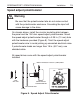

19
Installation
SPEEDMASTER™ OPERATION MANUAL
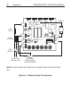
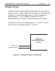
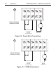
Figure 10. Voltage Follower Connections
Voltage follower
Instead of using a speed adjust potentiometer, the drive may be
wired to follow a voltage signal that is isolated from earth ground
(Figure 10). Connect the signal input (+) to S2. Connect the
signal common (–) to S1. Make no connection to S3. A
potentiometer can be used to scale the analog input voltage.
For 90 VDC motors, the voltage range is 0 - 1.4 VDC. For 180
VDC motors, the voltage range is 0 - 2.8 VDC.
LEESON
SPEEDMASTER™
DRIVE
S2
S1
Signal Input
Signal Common
+
-