OWNER’S MANUAL MANUALLY TUNED SYNTHESIZER STEREO RADIO WITH COMPACT DISC PLAYER DIGITAL
CONTENTS Installation .....................................................................................................3 DIN Front-Mount (Method A) ..................................................................................3 Installing the unit ...............................................................................................3 Removing the unit .............................................................................................4 DIN Rear-Mount (Method B) ....................
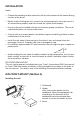
INSTALLATION Notes: • Choose the mounting location where the unit will not interfere with the normal driving function of the driver. • Before finally installing the unit, connect the wiring temporarily and make sure it is all connected up properly and the unit and the system work properly. • Use only the parts included with the unit to ensure proper installation. The use of unauthorized parts can cause malfunctions.
1. Dashboard 1 2. Nut (5mm) 6 3. Spring washer 7 4 2 4. Screw (5 x 25mm) 5 5. Screw 3 6. Strap Be sure to use the strap to secure the back of the unit in place. The strap can be bent by hand to the desired angle. (Fig. 2) 7. Plain washer Removing the unit 1. Frame 2. Insert fingers into the groove in the front of frame and pull out to remove the frame. (When re-attaching the frame, point the side with a groove downwards and attach it.) 3.
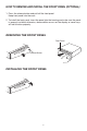
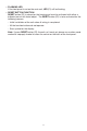
HOW TO REMOVE AND INSTALL THE FRONT PANEL (OPTIONAL) 1. Press the release button and pull-off the front panel. Keep front panel into the case. 2. To install the front panel, insert the panel into the housing and make sure the panel is properly installed, otherwise, abnormalities occurs on the display or some keys will not function properly.
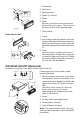
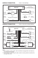
WIRING CONNECTION FOR 2 X 7W SYSTEM CD CHANGER CONNECTOR SOCKET (FOR CD CHANGER VERSION ONLY) MAIN UNIT (GREY) ANTENNA CONNECTOR RCA CABLE Rch RED CHOKE BOX MEMORY BACK-UP YELLOW GROUND (B–) POWER ANTENNA Lch SPEAKER Lch WHITE BLACK (FOR RCA LINE OUT VERSION ONLY) FUSE BLUE RED (FOR POWER ANT.
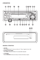
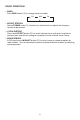
OPERATION 4 5 17 18 16 19 3 20 6 7 14 12 8 13 9 15 10 1 11 22 21 GENERAL OPERATION • ON/OFF Press PWR button (1) to turn on the unit. Press it again to turn it off. • FACEPLATE RELEASE Press REL button (2) to detach the removable faceplate. • LOUDNESS Press LOU/RND button (8) shortly to reinforce the bass output.
• SET THE CLOCK Press DSP button (9) to change the display to clock display. Press it again to return to previous display. In clock display, press and hold the DSP button (9) for several seconds until the clock display flashes. Press VOL (5) to change minutes or VOL (4) to change hours. • SELECT MODE Press SEL button (3) to change audio mode through volume, bass, treble, balance, and fader modes. Use VOL (4) and VOL (5) buttons to adjust the selected mode.
• FLASHING LED If the front panel is not on the main unit, LED (21) will be flashing. • RESET BUTTON FUNCTION RESET button (22) is placed on the housing and must be activated with either a ballpoint pen or thin metal object. The RESET button (22) is to be activated for the following reasons: - Initial installation of the unit when all wiring is completed. - All the function buttons do not operate. - Error symbol on the display.
RADIO OPERATION • BAND Press BND button (10) to change bands as below: FM MW LW • SELECT STATION Rotate TUNING knob (11) clockwise or anticlockwise to adjust the frequency upward or downward. • LOCAL/DISTANT Press the LOC/RPT button (12) to select between local setting for reception of strong station and distant setting for reception of weak stations when tuning. • MONO/STEREO In FM band, press MON/INT button (13) to select mono or stereo reception for radio stations.
CD OPERATION • DISC PLAY Gently insert a compact disc with the label side facing up into the disc slot (16). The disc is then automatically loaded into the unit and starts playing with the first track of the disc. The digital display will indicate the track number and the time of the track. • EJECT Press (eject) button (15) to stop CD play and eject CD from slot. Receiver switches to radio operation. • PAUSE CD During CD playing, press button (14) to temporarily stop playing.
SPECIFICATION GENERAL Power Supply Requirements Chassis Dimensions Tone Controls - Bass (at 100 Hz) - Treble (at 10 KHz) Maximum Output Power - Version V - Low Power Version Current Drain - Version V - Low Power Version : DC 12 Volts, Negative Ground : 178 (W) x 163 (D) x 50 (H) mm : +10 dB / –10 dB : +10 dB / –10 dB : 7W x 4 (ch) or 25W x 2 (ch) : 7W x 2 (ch) : 5 Ampere (FOR NORMAL POWER) : 3 Ampere (FOR LOW POWER) CD PLAYER Signal to Noise Ratio Channel Separation Frequency Response : More than 60 dB :
TROUBLE SHOOTING Before going through the check list, check wiring connection. If any of the problems persist after check list has been made, consult your nearest service dealer. Symptom No power. Disc cannot be loaded or ejected. Cause Solution The car ignition switch is not on. If the power supply is properly connected to the car accessory terminal, switch the ignition key to “ACC”. The fuse is blown. Replace the fuse. Presence of CD disc inside the player.