
Installation Guide

15A & 20A Ground Continuity Monitoring
Straight Blade Plugs & Connectors
15A Ground Continuity Monitoring
Turnlok Plugs & Connectors
20A & 30A Ground Continuity Monitoring
Turnlok Plugs & Connectors
** Use appropriate instructions for wiring angle plugs (included) **
WARNING: IMPROPER WIRING OF ANY ELECTRICAL DEVICE CAN
CAUSE SERIOUS INJURY OR DEATH. THESE WIRING DEVICES SHOULD
BE INSTALLED BY AN ELECTRICIAN OR OTHER QUALIFIED PERSON.
NOTICE: Connect only copper or copper clad wire to this device. Do not use
in medical equipment. Wiring errors can only be detected between the ground
continuity monitor and the source (circuit breaker). Do not use with catalog
numbers EHU15AN, L15AN, L20303AN, L203045AN.
AC ONLY
Proper grounding is assured only when the Bright Green light is visible.
THIS PRODUCT:
• Is a UL listed circuit tester suitable for determining ground continuity and
power status ONLY.
• Is not a comprehensive diagnostic instrument, but a simple instrument to
detect many probable common improper wiring conditions.
• Will not indicate quality of ground
• Will not detect two (2) hot wires in circuit
• Will not indicate reversal of Neutral (white) and Ground (green) wires.
• Is not suitable for damp or wet locations.
LED INDICATION:
Bright Green LED Indicator - Grounded and properly wired
Red LED or Red LED + Green LED Indicator - Open ground, reversed
polarity
No Indicator - Open hot, open neutral, hot and ground reversed. (Note:
Proper hot + GND, but open neutral may cause a dim green indication.)
*Refer all indication problems to a qualified electrician.
ALL INDICATORS REFER TO WIRING UPSTREAM OF THIS DEVICE
WIRING INSTRUCTIONS FOR: 15 & 20A Ground Continuity Monitoring
Straight Blade Plugs & Connectors
15A Ground Continuity Monitoring Turnlok Plugs & Connectors
1. WIRE SIZE AND RANGE FOR ROUND CORDS ONLY.
Cord diameter .230" to .720". Dust seal wire ranges .230" to .450". Remove
for wire sizes outside optimal range.
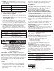
2. WIRE PREPARATION.
Insert cable into back housing through cord clamp
and dust shield (where applicable). Strip wire insu-
lation and cord jacket as shown in Figure 1. Do not
tin conductors.
3. WIRE TERMINATIONS.
Insert all stripped conductors fully into proper
wire termination holes as per Table 1. Tighten
termination screws securely with 14 inch pounds torque.
4. ASSEMBLY.
Slide cover up cord and over wired body. Tighten assembly screws, securely
attaching body to cover. Tighten cord clamp screws to 8-10 inch pounds
torque.
Table 1.
Terminal Ident. Conductor Ident.
Ground or Green Color Green insulation for equipment ground only.
White (Silver) White or gray insulation for neutral only.
WIRING INSTRUCTIONS FOR: 20 & 30A Ground Continuity Monitoring
Turnlok Plugs & Connectors
1. CORD DIAMETER AND SIZE
• 3-wire device: .385" (18/3 SJ Type) to .750" (8/3 S Type).
• 4-wire device: .385" (18/4 SJ Type) to .710" (6/4 S Type) with insert.
2. WIRE PREPARATION. Strip wire insulation and cord jacket
as shown in Figure 2. Do not tin conductors.
3. WIRE TERMINATIONS. Insert cord through cover
beginning from stripped conductors end. Insert
all stripped conductors fully into proper wire termina-
tion holes as per Table 2 (see below). Tighten termi-
nation screws securely with 14 inch pounds torque.
4. ASSEMBLY. Slide cover up cord and over wired body, noting keying of
body to cover. Tighten assembly screws, securely attaching body to cover.
Tighten cord clamp screws to 14 inch pounds torque, alternating between
screws, Snap dust boot over body.
Table 2.
Terminal Ident. Conductor Ident.
Ground or Green Color Green insulation for equipment ground only.
White (Silver) White or gray insulation for neutral only.
X, Y or Z Red, black, etc. insulation for hot conductor only.
** Use appropriate instructions for wiring angle plugs (included) **
Conectores y enchufes de cuchillas rectas de 15A y 20A con
monitoreo de continuidad de la conexión a tierra
Conectores y enchufes Turnlok de 15 A con monitoreo
de continuidad de la conexión a tierra
Conectores y enchufes Turnlok de 20 A y 30 A con
monitoreo de continuidad de la conexión a tierra
**Siga las instrucciones apropiadas para cablear los enchufes angulares (incluidas)**
ADVERTENCIA: EL CABLEADO INCORRECTO DE UN DISPOSITIVO
ELÉCTRICO PUEDE CAUSAR LESIONES GRAVES O AÚN LA MUERTE. UN
ELECTRICISTA U OTRA PERSONA COMPETENTE DEBE INSTALAR
ESTOS DISPOSITIVOS DE CABLEADO.
AVISO: Sólo utilice alambres de cobre o cobrizados con este dispositivo. No
utilizar en equipo médico. Los errores de cableado sólo pueden detectarse entre
el monitor de continuidad de la conexión a tierra y la fuente (cortacircuitos). No
utilizar con las unidades con número de catálogo EHU15AN, L15AN, L20303AN,
L203045AN.
CA ÚNICAMENTE
La conexión a tierra correcta sólo se garantiza cuando se ve la luz Verde
Intenso.
ESTE PRODUCTO:
• Es un verificador de circuito aprobado por UL que permite determinar la
continuidad de la conexión a tierra y la condición del suministro eléctrico
ÚNICAMENTE.
• No es un instrumento de diagnóstico completo, sino que más bien un
instrumento sencillo para detectar muchas condiciones comunes de
cableado inapropiado.
• No indicará la calidad de la conexión a tierra.
• No detectará dos (2) alambres cargados en un circuito.
• No indicará la inversión de los alambres neutro (blanco) y de conexión a
tierra (verde).
• No es apropiado para lugares húmedos o mojados.
INDICACIÓN DEL DIODO LUMINISCENTE:
Verde Intenso – conectado a tierra y cableado correcto
Rojo o Rojo + Verde – conexión a tierra defectuosa, polaridad invertida
No hay indicación – conductor cargado sin conectar, neutro sin conectar,
conductor cargado y conexión a tierra invertidos (Nota: Conductor cargado y
conexión a tierra correctos, pero con neutro sin conectar se podría indicar con
un diodo luminiscente verde tenue.)
*Refiera todos los problemas a un electricista competente.
TODOS LOS INDICADORES SE REFIEREN AL CABLEADO ENTRE EL
DISPOSITIVO Y EL CORTACIRCUITOS.
INSTRUCCIONES DE CABLEADO PARA: Conectores y enchufes de
cuchillas rectas de 15 y 20 A con monitoreo de continuidad de la conexión a tierra
Conectores y enchufes Turnlok de 15 A con monitoreo de continuidad de la
conexión a tierra
1. TAMAÑO Y RANGO DE ALAMBRE PARA CORDONES REDONDOS
ÚNICAMENTE. Diámetro del cordón: 0,230 pulg. a 0,720 pulg. Rango del
sello contra el polvo: 0,230 pulg. a 0,450 pulg. Retírelo para tamaños de
alambre fuera del rango óptimo.
2. PREPARACIÓN DE LOS ALAMBRES. Introduzca el cable en la caja
posterior a través de la abrazadera del cordón y la pantalla contra el polvo
(cuando corresponda). Desforre el aislamiento de los cables y la funda de
protección del cordón eléctrico, tal como se muestra en la Figura 1. No
estañe los conductores.
3. TERMINACIONES DE LOS ALAMBRES. Introduzca por completo todos
los conductores desforrados en los agujeros de terminaciones de cables
apropiados, de acuerdo con la Tabla 1. Apriete bien los tornillos de las
terminaciones aplicando 14 pulg.-lbs. de par de torsión.
1≤
1/2≤
Figure 1
Figure 2
INSTALLATION
INSTRUCTIONS
INSTRUCCIONES DE
INSTALACIÓN PARA