
Installation Guide

2
D
E
F
G
H
L
K
J
I
C
B
A
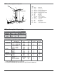
* 20% cable fill is calculated to approximate reduction in cable capacity due to connectors mounted within
raceway and fittings that may restrict cross sectional area.
** 40% cable fill is the maximum designed cable fill based on a proposed revision to TIA/EIA 569-A.
O.D. 500 SERIES
CABLE/WIRE SIZE inches [mm] 20% FILL* 40% FILL**
UNSHIELDED 4-pair, 24 AWG, Cat 3 0.190 [4.8] 1 2
TWISTED PAIR 4-pair, 24 AWG, Cat 5e 0.210 [5.3] 1 2
4-pair, 24 AWG, Cat 6 0.250 [6.3] 0 1
TELEPHONE 2-pair, 24 AWG 0.140 [3.6] 2 4
3-pair, 24 AWG 0.150 [3.8] 2 4
4-pair, 24 AWG 0.190 [4.8] 1 2
25-pair, 24 AWG 0.410 [10.4] 0 0
COAXIAL RG58/U 0.195 [5.0] 1 2
RG59/U 0.242 [6.1] 0 1
RG62/U 0.242 [6.1] 0 1
RG6/U 0.270 [6.9] 0 1
TWINAXIAL 100 Ohm 0.330 [8.4] 0 0
SHIELDED TYPE 1 0.390 [9.9] 0 0
TWISTED PAIR TYPE 2 0.465 [11.8] 0 0
TYPE 3 0.245 [6.2] 0 1
FIBER Mini ZipCord 0.079 x 0.157 [2 x 4] 3 6
ZipCord 0.118 x 0.236 [3 x 6] 1 2
Round 4 Strand Fiber 0.187 [4.8] 1 2
Round 6 Strand Fiber 0.256 [6.5] 0 1
V500 Series Raceway Wire Fill Capacities for Communications
WIRE SIZE O.D. NO. OF CONDUCTORS
THHN/THWN inches [mm] V500 SERIES (40% FILL)
14 AWG 0.111 [2.8] 7
12 AWG 0.130 [3.3] 5
10 AWG 0.164 [4.2] 3
V500 Series Raceway Wire Fill Capacities for Power
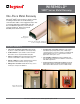
A — V5751 Starter Box
B — V500+ 10' Raceway
C — B9-10-11 Supporting Clip (Included)
D — B9-10-11 Cover Clip (Included)
E — B9-10-11 Mounting Strap (Included)
F — B16 Tee Fitting
G — B6 Flat Elbow
H — B1 5' Raceway
I — V5733AF Fan Box Solid Base
J — V5748 1 3/4" Deep Device Box
K — V5747-2 2-Gang Box
L — B8 Outside Elbow
M — B7 Inside Elbow
N — V5747 1 3/8" Deep Device Box
V500 Series Raceway Wire Fill Capacity Charts
V500 Series Raceway System Components
N
M
Key