KEOR T 10 – 60 KVA INSTALLATION MANUAL
Important Notices! Thank you for choosing LEGRAND UPS System to supply your Critical Application. This manual contains important information about commissioning, usage and technical properties of the UPS. It also contains safety information for operator and instructions to secure your critical load. Applying the recommendation detailed in this manual is necessary to use UPS safely and correctly.
Description of the Symbols Used in the Manual This symbol points out the instructions which are especially important. This symbol points out the risk of electric shock if the following instruction is not followed. This symbol points out the instructions, which may result with injury of the operator or damage of the equipment if not followed. All packing material must be recycled in compliance with the laws in force in the country where the system is installed.
Battery Fast Fuses Installation & Operating Manuals IV
INDEX 1. FOREWORD ........................................................................................................................................ 1 1.1. Overview ..................................................................................................................................... 1 1.2. Manual ........................................................................................................................................ 1 2. WARRANTY...........................................
1. FOREWORD 1.1. Overview Thank you for choosing LEGRAND UPS Keor T product. KEOR T has been designed with advanced technologies and the latest components generation; realized to satisfy both users and installers in their operational needs of high availability and performance. This UPS aims to be efficient, functional, safe and very easy to install and use. LEGRAND has studied the best way to reconcile high-tech performance and ease of use, making “user friendly” technologically advanced products.
• The manual must be kept for the equipment’s useful life cycle and, if necessary (e.g. damage which prevents it being consulted even partially) the user must ask the Manufacture for a new copy, quoting the publishing code on the cover. • The manual reflects the state of the art at the moment the equipment was put on the market, of which it is an integral part. The publication complies with the directives in force at such a date.
2. WARRANTY 2.1. Terms of Warranty • • • Warranty period begins from the date of commissioning of the UPS by authorized LEGRAND UPS Technical Service staff or authorized LEGRAND distributor Technical Service Staff. The UPS including all the internal parts is under the warranty of LEGRAND.
3. SAFETY Information related to safety of the UPS, battery, load and the user is summarized below. But the equipment should not be installed before reading the manual completely. 3.1. Description of the Symbols Used on the Labels Applied to the UPS PE: PROTECTIVE EARTH PB: PROTECTIVE BOUNDING DANGER! HIGH VOLTAGE (BLACK/YELLOW) This symbol points out the instructions, which may result with injury of the operator or damage of the equipment if not obeyed. 3.2.
3.3. Important Notice for UPS • • • • • • • • • • • • • • • • The equipment may only be installed and commissioned by authorized LEGRAND UPS Technical Service Personnel. This manual contains important instructions that you should follow during installation and maintenance of the UPS and batteries. Please read all instructions before installing the equipment and save this manual for future reference.
3.4. Important Notice for Battery • • • • • • • • • The batteries may only be installed and commissioned by authorized LEGRAND UPS Technical Service Personnel. Make sure that the battery qty is proper for the unit and they are same type and capacity. Otherwise danger of explosion and fire is within the bounds of possibility. Do not dispose of batteries in a fire. The batteries may explode. Do not open or mutilate batteries. Released electrolyte is harmful to the skin and eyes. It may be toxic.
4. REQUIREMENT 4.1. Transportation The UPS must be placed and stand in a vertical position throughout the transportation. Use suitable equipment to remove the UPS from the pallet. The equipment shall be packed properly during transportation. Therefore it is recommended to keep the original package for future need. All packing material must be recycled in compliance with the laws in force in the country where the system is installed. 4.2.
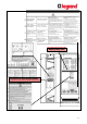
Figure.4.2-1 Figure.4.2-2 Climatization Ventilation Direction of ventilation is front/sides to back. The room should be equipped with ventilation system or air conditioning to collect warm air from the top of the room and provide cool air at the bottom. Figure.4.
In order to profit from optimal ventilation, the side panels must remain in place for UPS with internal battery. The UPS should be mounted on a concrete surface and non-combustible surface. 4.3. Storage Please store the UPS in an environment where the temperature is between -25°C + 55°C, no receipt of direct sunlight, far from the heating, in a dry place. Environmental humidity must be between 20-95% (non-condensing).
Installation Parameters Model (kVA) 10 15 30 40 60 Phase in/out Rated output apparent power (kVA) 10 15 3Ph+N/3Ph+N 20 30 40 60 Rated output active power (kW) 9 13,5 18 27 36 54 14 21 28 42 57 84 18 27 36 54 72 105 15 22 29 44 58 87 19 28 36 55 73 109 15 22 29 44 58 87 19 28 36 55 73 109 10 min 11,3 16,9 22,5 33,8 45 67,5 1 min 13,5 20,3 27 40,5 54 81 D curve circuit breaker (A) (3-pole) 20 25 40 50 63 100 GG fuse (A) 20 25 40 5
5. INSTALLATION When the UPS is delivered, examine the packaging and product carefully to see if any damage occured during transport. If either possible or ascertained damage is found report it immediately to: • the carrier; • LEGRAND Technical Assistance Center. Make sure that the unit received corresponds to the material specified on the delivery document. The UPS Keor T packaging protects the equipment against mechanical and environmental damages.
5.2. Unpacking Procedure Figure.5.2-1 Remove the wrap and the package. Figure.5.2-2 Figure.5.2-3 Place UPS in the installation area.
Figure.5.2-4 Remove the side parts which prevent the transpallet to damage the UPS. Unload the UPS from the pallet. It is recommended to store the original UPS packaging for future needs. 5.3. Installation Procedures and Instructions The equipment may only be installed and commissioned by authorized LEGRAND UPS Technical Service Staff or authorized LEGRAND distributor Technical Service Staff. When the UPS is brought from a cold place to a warmer place, humidity of the air may condensate in it.
5.3.1. Power Connections Make sure that all circuit breakers are “OFF” before starting with the installation. The power screw terminals are located on the lower front side of the UPS. Firstly, open the UPS door, screw out of the metal cover, afterwards open plastic cover of terminals. After the covers are removed, the cables shall be passed through the hole under the terminals. After all connections done, replace the covers in order. Figure.5.3.1-1 Figure.5.3.1-2 Figure.5.3.
Figure.5.3.1-6 Power Cables Path Figure.5.3.1-7 Communication Cables Path Figure.5.3.1-8 Fix the plinths delivered with the UPS after all cable installation done.
10-30kVA (3Ph Input – 3Ph Output) Circuit Breakers Figure.5.3.
10-30kVA (3Ph Input – 3Ph Output) Connection if the MAINS and AUX Supply are connected in COMMON Figure.5.3.
10-30kVA (3Ph Input – 3Ph Output) Connection if the MAINS and AUX Supply are connected SEPARATELY Figure.5.3.
40-60kVA (3Ph Input – 3Ph Output) Circuit Breakers Figure.5.3.
40-60kVA (3Ph Input – 3Ph Output) Connection if the MAINS and AUX Supply are connected in COMMON Figure.5.3.
40-60kVA (3Ph Input – 3Ph Output) Connection if the MAINS and AUX Supply are connected SEPARATELY Figure.5.3.
Connections shall be made in the following order; 5.3.1.1. Earth Connection The device shall be earthed for a safe and reliable operation. Connect the PE/PB ground terminals before connecting any other cable. Figure.5.3.1.1-1 Input Mains Supply’s Protective Earth terminal PE of the UPS shall be connected to the ground with a low impedance connection.
Please add three-pole (3-pole) MCCB to distribution panel for UPS’s input. Do not connect any other load to it. Connect the phase cables to X1 MAINS SUPPLY: X1/L1 - X1/L2 - X1/L3 terminals, the neutral to X1 MAINS SUPPLY: X1/N terminal. Neutral connection should be done directly from distribution neutral bus to UPS neutral. If auxiliary supply exists, remove all bridges. When used, the residual current earth leakage protection system must be common for the two AC inputs and installed upstream.
Please add three-pole (3-pole) MCCB to distribution panel for UPS’s auxiliary input. If auxiliary supply exists, remove all bridges. Connect the phase cables to X4 AUXILIARY SUPPLY: X4/L1 - X4/L2 - X4/L3 terminals, the neutral to X4 AUXILIARY SUPPLY: X4/N terminal. Neutral connection should be done directly from distribution neutral bus to UPS neutral. 5.3.1.4. Battery Connection You may find more information about Keor T Models and Battery capacity in Section 5.1. Models and Dimensions.
KEOR-T 10-30kVA 1x60pcs 7-9Ah BATTERY WIRING DIAGRAM Figure.5.3.1.
KEOR-T 10-30kVA 2x60pcs 7-9Ah BATTERY WIRING DIAGRAM Figure.5.3.1.
KEOR-T 40-60kVA 2x60pcs 7-9Ah BATTERY WIRING DIAGRAM Figure.5.3.1.
KEOR-T 40-60kVA 3x60pcs 7-9Ah BATTERY WIRING DIAGRAM Figure.5.3.1.
External Battery Connection: If the batteries are in a separate additional battery cabinet, the cabinet should be supplied by the manufacturer. If battery cabinets not supplied by the manufacturer of Keor T, it is the installer’s responsibility to check the electrical compatibility and the presence of appropriate protection devices between the cabinet and Keor T.
Electrical Characteristics - Inverter Model (kVA) 10 Rated output voltage (selectable) (V) 15 20 30 40 60 400 3Ph + N (380/415 configurable) Output voltage tolerance static load ±1%, dynamic load VF-SS-111 compliant Rated output frequency (Hz) 50/60 Hz (selectable) Autonomous frequency tolerance ±0.02% on mains power failure Harmonic voltage distortion < 2% with linear load, < 4% with non linear load Tablo.
8. COMMUNICATION Interface connectivity cards allow UPS to communicate in a variety of networking environments and with different type of devices. Standard and optional communication interfaces are listed below; Communication Interfaces Model (kVA) 10 15 20 30 RS232 • RS485 / MODBUS • Dry Contacts • Generator Interface • Remote Emergency Switching Device (ESD) Interface • Internal SNMP / Web Monitoring / e-mail ◦ 40 60 ◦ External SNMP • Standard ◦ Option Tablo.7 1. 2. 3. 4. 5.
Communication Cable Path Figure.8-2 8.1. Serial Communication (RS232) UPS is equipped with Serial Communication as standard. RS232 cable shall be shielded and shorter than 25m. RS232: DSUB-9 male connector with the following pin layout shall be used on the UPS side of the connection cable. RS232 PIN LAYOUT PIN# Signal Name Signal Description 2 RX Receive Data 3 TX Transmit Data 5 GND Signal Ground Tablo.
Over SNMP communication, battery test can be started or current test can be cancelled. UPS can be shut-down or stand-by (stand-by duration is adjustable). Alarms can be discarded. If Serial Communication cable is needed, it can be produced according to the pin configuration described at side. 8.2. Internal SNMP Communication Internal SNMP card can be installed into SNMP slot placed at the front of UPS. As soon as SNMP installed, RS232 port would be disabled.
8.3. Emergency Switching Device and Generator Connections Voltage to be applied to the digital inputs is 5VDC. Maximum current drawn by each input is 1mA. 5VDC supply provided on the communication interface board can be used to supply both digital inputs. Figure.8.3-1 UPS output can be switched off immediately by Remote Emergency Switching Device interface (ESD) connection if desired. A remote latched switch can be used as described in above figure.
8.4. Dry Contacts 1 2 3 4 There are 4 dry contact sockets on the Interface Board. The relays can be programmable from Relay Functions menu (under Settings menu). “General alarm, Input failure, Battery failure, Output failure, Bypass active, Output overload, High temperature” alarms can be assigned to the contacts. Each alarm can be assigned to separate relays but also one alarm may be assigned to all relays.
8.5. RS485 RS485 with MODBUS protocol is used in a wide range of automation systems for Industrial Process monitoring or for Building Management Systems. This communication link allows monitoring UPS status and measurements with such systems. The RS485 differential line consists of three pins: • • • A is inverting pin (TxD-/RxD-) B is non-inverting pin (TxD+/RxD+) Middle Pin is reference pin (optional GND) Middle Pin is the reference potential used by the transceiver to measure the A and B voltages.
Appendix-1: Technical Specifications Tower Model (3Ph/3Ph) KEOR T 10KVA KEOR T 15KVA KEOR T 20KVA KEOR T 30KVA KEOR T 40KVA KEOR T 60KVA Output Power (VA) 10.000 15.000 20.000 30.000 40.000 60.000 Nominal Active Power (W) 9.000 13.500 18.000 27.000 36.000 54.
COMMUNICATION* Standard Interface RS232, ESD, Genset, Modbus, 4 Programmable Relay Contacts Options USB Converter, SNMP Generex or Megatec Protocol ENVIRONMENT Operating Temperature Range (⁰C) 0 - 40 Battery Temperature Range (⁰C) 20 - 25 (Recommended For Longer Battery Life) Maximum Altitude without Derating (m) Relative Humidity Range 1000 20-95% (Non-Condensing) Acoustic Noise (dBA) < 55 (at 1m) PYHSICAL Dimensions (HxWxD) (mm) Weight (kgs) (Model 0) Paint 1345/1650 x 400 x 800 118 132 134
Appendix-2: Modbus List While reading data through MODBUS, the following addresses can be used. "03 - Read Holding Registers" must be selected to read the MODBUS data. We can send commands by using MODBUS. To do that function 06 – Write Single Register must be used. The data is defined as unsigned words (2 bytes).
Also we can use addresses 127 to get the UPS status. A decimal value will be received from address 127. If that value is converted to binary number, the UPS status can be read.
Appendix-3: Description of UPS and Block Diagram SEPARATED RECTIFIER AND BYPASS INPUTS 41
COMMON RECTIFIER AND BYPASS INPUTS 42
Name Definition Q1 Common Mains Supply Circuit Breaker Q2 Output Circuit Breaker Q3 Maintenance Bypass Circuit Breaker Q4 Auxilary Mains Supply Circuit Breaker F5 Battery Fast Fuse Q6 Inrush Circuit Breaker F1 Rectifier Fast Fuse F2 Inverter Fast Fuse KREC Rectifier Contactor KINV Inverter Contactor KBYP Backfeed Contactor X1 Common Mains Supply Terminals X2 Output Terminals X4 RECTIFIER Auxiliary Mains Supply Terminals In case any inverter fault occurs; Bypass thyristors trans