
Installation Guide

To be installed by a certified
electrician or other qualified person.
WARNING – To prevent severe shock or electrocution, always turn power
OFF at the service panel before installing this unit, working on the circuit, or
changing a lamp.
CAUTION – To reduce the risk of overheating and possible damage to other equipment,
do not install incandescent dimmer to control a receptacle, a fluorescent light, a motor-
operated appliance, or a transformer-supplied appliance.
Do not use dimmer with incandescent lamps whose power requirements
exceeds maximum power (stated in Watts) of the dimmer.
Do not connect dimmer to power source other than 120VAC, 60 Hz only.
Use copper wire only.
DIRECTIONS
1. Disconnect power to circuit by removing fuse or turn circuit breakers OFF
before installing.
2. Remove wall plate and switch mounting screws, pull existing switch from
wall box.
3. Disconnect existing switch from circuit. 3-way installation: Identify the
“COMMON” wire (wire connected to the terminal marked common or odd
colored terminal). For “new” installation identify wire connected to power
source or to the load.
4. Connect dimmer as shown in the installation diagram using #12 or #14
AWG stranded or solid copper conductors. Strip wire using gauge on back
of device.
5. Install dimmer in wall box, with word ‘TOP’ on the strap right side up, using
mounting screws provided.
6. Attach wall plate, then restore power to circuit. NOTE: It is necessary to
remove knob on Short Slide version before attaching wall plate.
NOTE: It is normal for the dimmer to feel warm during operation. A 50W
minimum load is required. Use a separate neutral wire for each phase of a
multiphase system containing a dimmer, and for high power single phase
applications where flickering is present.
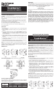
DIMMER TYPES
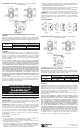
MULTIPLE GANGING OF DIMMERS
Any combination of dimmer models and other devices may be ganged
together. Dimmers can be ganged without removing fins. De-rate the maximum
load according to the following table.
MAXIMUM
GANG REDUCTION
LOAD
2 DIMMERS 3+DIMMERS
600W 500W 400W
1000W 700W 650W
WARRANTIES
Lifetime Warranty. The device you have purchased is warranted under normal
use against defects in workmanship and materials for as long as you own the
device. If the device fails due to manufacturing defect during normal use, return
the device for replacement to the store where purchased or send to:
Pass & Seymour Legrand
50 Boyd Avenue
Syracuse, NY 13209
All requests for replacement must include a dated sales receipt (legible copies
acceptable).
ALL OTHER WARRANTIES, INCLUDING BUT NOT LIMITED TO ANY
WARRANTIES OF MERCHANTABILITY OR FITNESS FOR A PARTICULAR
PURPOSE, ARE LIMITED TO A PERIOD OF TWO YEARS FROM THE
DATE OF PURCHASE. YOUR SOLE AND EXCLUSIVE REMEDY AGAINST
PASS & SEYMOUR LEGRAND UNDER ANY WARRANTY SHALL BE THE
EQUIVALENT REPLACEMENT OF THE DEVICE. IN NO EVENT SHALL ANY
WARRANTY APPLY TO ANY DEFECT ARISING OUT OF ANY ALTERATION
OF THE DEVICE, IMPROPER WIRING, IMPROPER INSTALLATION, MISUSE,
ABNORMAL USE OR NEGLIGENCE. IN NO EVENT SHALL PASS &
SEYMOUR LEGRAND BE LIABLE FOR LOST PROFITS, INDIRECT, SPECIAL,
EXEMPLARY, INCIDENTAL OR CONSEQUENTIAL DAMAGES. Some states
do not allow limitations on how long implied warranties last and do not allow
exclusion or limitation of incidental or consequential damages. Some of the
above limitations or exclusions may not apply to every purchaser.
Para ser instalado por electricista certificado u otra persona capacitada.
ADVERTENCIA: Para prevenir una sacudida eléctrica severa o electrocución,
siempre CORTE la electricidad en el panel de servicio antes de instalar esta
unidad, trabajar en el circuito, o cambiar una lámpara.
AVISO: Para reducir el riesgo de recalentamiento y posiblemente dañar a
otro equipo, no instale el reductor de luz incandescente para controlar un
receptáculo, una luz fluorescente, un artefacto motorizado, o un artefacto
alimentado por un transformador.
No use el reductor de luz con lámparas incandescentes cuyas requisitos de
potencia exija la potencia máxima (indicada en Wats) del reductor de luz.
No conecte al reductor de luz a otra fuente de potencia que no sea solo
120VAC, 60Hz.
Solo utilice cables de cobre.
INSTRUCCIONES:
1. Corte la electricidad al circuito en el panel quitando el fusible o APAGANDO
el interruptor automático antes de la instalación.
2. Quite la chapa de pared y los tornillos de montura de chucho, hale el
chucho existente de la caja embutida en la pared.
3. Desconecte el chucho existente del circuito. Instalación de tres
direcciones: Identifique el cabe “COMÚN” (el cable conectado al la
terminal marcada “común - common” o la terminal colorada con un color
singular). Para instalación “nueva” identifique el cable conectado al la
fuente de potencia o a la carga.
4. Conecte el reductor de luz como mostrado en el diagrama de instalación
utilizando alambre trenzado o sólido #12 o #14 AWG de cobre. Pele el
alambre utilizando la guÌa en la parte trasera del aparato.
5. Instale el reductor de luz en una caja de pared con la palabra “TOP” en la
correa hacia arriba, utilizando los tornillos de montaje proveídos.
6. Fije la chapa de pared, entonces restáurele la corriente al circuito. NOTA:
Es necesario quitarle la perilla en la versión de Deslice Corto antes de fijar
la chapa de pared.
NOTA: Es normal que el reductor de luz se sienta caliente durante su
funcionamiento. Una carga mínima de 50W es requerida. Use un cable neutral
separado para cada fase de un sistema polifásico que tiene un reductor de
luz, y para aplicaciones de una fase de alta potencia donde ocurre centelleo.
TIPOS DE REDUCTORES DE LUZ
INSTALLATION INSTRUCTIONS
TradeMaster
®
INCANDESCENT DIMMERS
R E A D A N D S A V E T H E S E I N S T R U C T I O N S !
Toggle
Decorator Slide
Short Slide
Single Pole Three Way
INSTALLATION DIAGRAM (wiring is same with each of dimmer types)
INSTRUCCIONES EN ESPAÑOL
L E A Y G U A R D E E S T A S I N S T R U C C I O N E S
INSTRUCCIONES DE INSTALACIÓN
TradeMaster
®
REDUCTORES DE LUZ INCANDESCENTE
Deslice de Decoracíon
Volquete
Deslice Corto