
Installation Guide

No: 341157
WattStopper
®
radiant
®
Dimmers: CFL/LED 450W, 120VAC, 60Hz; Incandescent 700W, 120VAC, 60Hz
Gradateurs radiant
®
: CFL/LED 450 W, 120 VCA, 60 Hz; Incandescents 700 W,
120 VCA, 60 Hz
Atenuadores radiant
®
: CFL/LED 450 W, 120 VCA, 60 Hz; Incandescente: 700 W,
120 VCA, 60 Hz
Installation Instructions • Instrucciones de Instalación • Notice d’Installation
Catalog Number(s) • Numéro(s) de Catalogue • Les Numéros de Catalogue: RHCL453P
Country of Origin: Made in China • Pays d’origine: Fabriqué en Chine • País de origen: Hecho en China
READ AND SAVE THESE INSTRUCTIONS
To be installed by a certified electrician or other qualified
person.
WARNING – To prevent severe shock or electrocution,
always turn power off at the service panel before
installing this unit, working on the circuit, or changing
a lamp.
CAUTION: To reduce the risk of overheating and
possible damage to other equipment:
• Do not install dimmer to control a receptacle, a
motor-operated appliance, or a transformer-supplied
appliance.
• Use only with incandescent or compatible dimmable
CFL/LED bulbs which screw into conventional
incandescent lamp sockets (compatible bulbs listed
at www.legrand.us).
Connect to 120VAC, 60 Hz power source only.
A 10W minimum load is required.
Use copper wire only.
LIRE ET CONSERVER CES INSTRUCTIONS
Doit être installé par un électricien certifié ou une autre
personne qualifiée.
AVERTISSEMENT – Pour éviter tout choc électrique ou
une électrocution, toujours couper l’électricité au niveau
du panneau d’alimentation avant d’installer cette unité,
de travailler sur le circuit électrique ou de changer une
lampe.
ATTENTION : Pour réduire le risque de surchauffe ou
d’endommagement d’autres pièces d’équipement :
• Ne pas installer un gradateur pour contrôler une
prise électrique, ou un appareil ménager équipé d’un
moteur ou alimenté par un transformateur.
• À n’utiliser qu’avec des ampoules à incandescence ou
variable à luminosité CFL/LED ampoules compatibles
qui se vissent dans des douilles d’ampoules à
incandescence traditionnelles (ampoules compatibles
énumérés à www.legrand.us).
Connecter à une source de 120 VCA, 60 Hz
uniquement.
Une charge minimale de 10W est requise.
N’utiliser que des fils en cuivre.
LEA Y CONSERVE ESTAS INSTRUCCIONES
Para ser instalado por un electricista certificado o
persona competente.
ADVERTENCIA – Para evitar descargas eléctricas
serias o electrocución, antes de instalar, trabajar en
el circuito o cambiar una lámpara de este atenuador
apague siempre el suministro eléctrico en el panel de
servicio.
PRECAUCIÓN: Para reducir el riesgo de
sobrecalentamiento y posibles daños a otros equipos:
• No instale un atenuador para controlar un
tomacorriente, un electrodoméstico que funciona con
motor o un electrodoméstico con transformador.
• Utilícese solamente con bombillas incandescentes
CFL o LED atenuables que se atornillan en
portalámparas incandescentes convencionales
(bombillas compatibles enumerados en www.legrand.us).
Conecte solamente a un suministro eléctrico de 120
VAC, 60 Hz.
Una carga minima de 10W es requerida.
Utilice únicamente alambres de cobre.
IMPORTANT NOTES:
1. All dimmers can be damaged by improper wiring. Check for short circuits prior to
installing the dimmer.
Procedure for short circuit check:
a. Disconnect power to circuit by removing fuse or turn circuit breakers OFF.
b. Install a switch instead of the dimmer. Turn the switch to the “ON” position.
c. Turn power ON. If the circuit breaker trips, a short is present. If the light fails
to turn ON and OFF with the switch, the wiring may be incorrect.
d. Correct wiring, if necessary and retest.
e. Install the dimmer only after the light operates properly with the switch.
2. Protect from dirt and dust. The dimmer can be damaged from contaminates
encountered during the construction process. If lighting is required prior to the
construction process completion, then a switch should be temporarily installed
in place of the dimmer. The dimmer should not be installed until the construction
process is complete.
Any dimmer damage due to improper installation is not covered under warranty.
COLOR CHANGE PROCEDURE / PROCEDIMIENTO DE CAMBIO DE COLOR /
PROCÉDURE DE CHANGEMENT DE COULEUR
DIRECTIONS
1. If a color change kit was provided, and a different color is desired, see the Color
Change Procedure, if not proceed to step #2.
2. Disconnect power to circuit by removing fuse or turn circuit breakers OFF
before installing.
3. Remove wall plate and switch mounting screws, pull existing switch from wall box.
4. Disconnect existing switch from circuit. For 3-way installations: Identify the
“Common” wire (wire connected to the terminal marked common or odd colored
terminal). For new installation identify wire connected to power source or to the load.
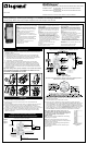
5. Connect dimmer as shown in the installation diagram using #12 or #14 AWG
stranded or solid copper conductors. Strip wire using gauge on back of device
(Figure 1 or Figure 2).
INSTALLATION DIAGRAM FOR DIMMERS
SCHÉMA D’INSTALLATION DES GRADATEURS
DIAGRAMA DE INSTALACIÓN PARA ATENUADORES
Single Pole Installation / Installation unipolaire / Instalación unipolar
3-Way Installation / Installation 3 voies / Instalación de 3 vías
Screw Pressure Plate Back Wire / Fil arrière avec vis et plaque de pression /
Cable trasero con tornillo y placa de presión
6. Install dimmer in wall box, with word “TOP” on the strap right side up, using
mounting screws provided.
7. Attach wall plate and then restore power to circuit.
8. Dimmer may require adjustment to the low end setting to reliably start and/or
remove flickering in bulbs. To adjust, DISCONNECT POWER FROM CIRCUIT, and
remove the Wallplate. Use a small insulated, flat tipped screwdriver to adjust the
trim pot wheel, which is accessible via the slot (marked “CALIBRATION”) provided
on the strap (Figure 3). Turn the wheel downwards to increase the minimum light
intensity setting and turn the wheel upwards to decrease light intensity. Next,
install the Wallplate, restore the power and test. Repeat above as necessary.
Note: Never adjust trim pot when circuit is live. To
re-calibrate settings turn the trim pot wheel all the way
up towards the “-” sign and incrementally progress to
“+” sign until flickering is removed (refer
to Step 8 above).
Note: This device should be installed after sheet rocking
and painting are completed.
Note: It is normal for the dimmer to feel warm during
operation. Use a separate neutral wire for each phase of a
multiphase system containing
a dimmer, and for high power single phase applications
where flickering is present.
Any combination of dimmers and other devices may be
ganged together
Neutral (White) / Neutre (Blanc) / Neutro (Blanco)
120VAC 60 Hz
120 VCA 60 Hz
120 VCA 60 Hz
Hot (Black)
Chaud (Noir)
Cargado
(Negro)
Wire to Source
120VAC 60 Hz
Connecter à la source
120 VCA 60 Hz
Cable a suministro
120 VCA 60 Hz
Wire to Load
Connecter à
la charge
Cable a carga
White
Blanc
Blanco
Black
Noir
Negro
Do not wire this terminal
Ne pas raccorder cette borne
No cablear este borne
Green Ground Screw
Vis de terre verte / Tornillo verde de puesta a tierra
LIGHT
LUMIÈRE
LUZ
Figure 1
Figure 1
Figura 1
1. 2.
4. 5.
3.
6.
Figure 2 / Figure 2 / Figura 2
Figure 3 / Figure 3 /
Figura 3
RHCL453P