
User manual

58
®
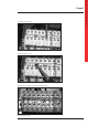
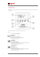
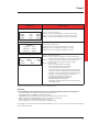
The images of the different main frame pages are given below.
MAIN PAGE DATA DISPLAYED
1 Input – output – battery
1st line: UPS operating status;
2nd line: Input voltages;
3rd line: Voltage set in output, active power absorbed by the load
and total load applied percentage
4th line: Bar showing residual battery capacity and actual time
of operation in the case of a power failure.
2 Input – percentage output – battery
1st line: UPS operating status;
2nd line: Input voltages;
3rd line: Load percentage on the phases in output;
4th line: Bar showing residual battery capacity and actual time
of operation in the case of a power failure.
3 Bypass – output – battery
1st line: UPS operating status;
2nd line: Bypass voltages;
3rd line: Voltage set in output, active power absorbed by the load
and total load applied percentage
4th line: Bar showing residual battery capacity and actual time
of operation in the case of a power failure.
4 Bypass – percentage output – battery
1st line: UPS operating status;
2nd line: Bypass voltages;
3rd line: Load percentage on the phases in output;
4th line: Bar showing residual battery capacity and actual time
of operation in the case of a power failure
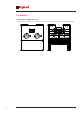
5 Load availability in output
1st line: UPS operating status;
2nd line: Phase L1: power in kVA or Watt with respect to nominal power
or current with respect to the nominal and relative percentage;
3rd line: Phase L2: power in kVA or Watt with respect to nominal power
or current with respect to the nominal and relative percentage;
4th line: Phase L3: power in kVA or Watt with respect to nominal power
or current with respect to the nominal and relative percentage
6 Measurements on the output
1st line: UPS operating status;
2nd line: Phase L1 in output: Voltage, current and active power;
3rd line: Phase L2 in output: Voltage, current and active power;
4th line: Phase L3 in output: Voltage, current and active power.
7 Output related voltages
1st line: UPS operating status;
2nd line: output: line voltage between phases L1 and L2;
3rd line: output: line voltage between phases L2 and L3;
4th line: output: line voltage between phases L3 and L1
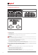
TRIMOD
BYP
λ
232V/231V/229V
OUT 0%/ 0%/ 0%
Batt. 12h
TRIMOD
L1o 0.4/ 40kVA 1%
L2o 0.5/ 40kVA 1%
L3o 0.5/ 40kVA 1%
TRIMOD
L1o231V 1.7A 27W
L2o229V 1.6A 31W
L3o231V 1.9A 29W
TRIMOD
L1o-L2o 400V
L2o-L3o 399V
L3o-L1o 396V
TRIMOD
IN
λ
230V/228V/227V
OUT 0%/ 0%/ 0%
Batt. 12h
TRIMOD
BYP
λ
230V/231V/229V
OUT
λ
230V 95W 0%
Batt. 12h
TRIMOD
IN
λ
230V/226V/227V
OUT
λ
230V 93W 0%
Batt. 12h
7. Control Panel