
Installation Guide

FRAME MOUNTING INSTRUCTIONS:
Note: Unit to be installed on finished wall, with a thickness of 1/8" to 1-1/16". Be sure
there are no obstructions behind wall surface, such as wall studs.
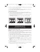
1) Place Frame facing wall in desired location and mark wall
through slots provided. Make sure there are no obstructions
behind wall before cutting.
2) Connect the marks and cut out wall surface. Cut Out
Dimensions: TV1W: 4-1/8" x 6-3/8" TV3W: 7-3/4" x 6-3/8"
3) Place Frame into cutout. Turn screws clockwise. Tighten until
snug against wall.
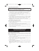
4) Insert P&S Signature™ end-cap tabs and firmly push to snap on.
Note: To remove Signature™ end-caps, insert small flat
screw driver into each notch and gently pry off. See figure 1.
A) Line Voltage or Low Voltage Mounting Capable. Use
appropriate installation instruction.
B) Low Voltage Only. Use keystone jacks for hard wired
terminations.
www.passandseymour.com (full line of keystone jack options.)
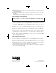
LINE VOLTAGE INSTALLATION:
Warning – To prevent severe shock or electrocution, always turn power OFF at the
service panel before installing this unit, working on the circuit, or changing a lamp.
1) A P&S old work electrical box must be used. P116W, S116W & S118W are recom -
mended for best fit. Check for clearances before installation to ensure proper fit.
Center opening on TV3W may not be suitable for line voltage in all applications. (2x4
wall construction)
2) Pull cable through desired opening. Insert nonmetallic cable into Auto/Clamp
®
cable
entry in the old work box.
3) Pull cable through to the desired length. Install UL listed Electrical devices per manu -
facturer’s instructions.
Recessed TV Box
Installation Instructions
P/N 340868 Rev. B
Fig. 1
TV3W TV1W
340868_Recessed TV Box IS:340868_RevB_RecesseVBox_IS 2/14/08 11:47 AM Page 2