
Owners Manual

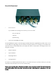

Switches/configuration
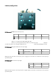
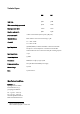
DIP-Switches 1/2 (MM/MC-selection and input load)
1 2 3 4
On
MC 1k *** 100R
Off
MM - - -
Switch nr. 1 is for gain selection (36dB = MM; 56dB = MC)
switches 2 to 4 are for input load selection. Switch nr. 3 activates the special impedance
slot. Please note that you can select gain and impedance load independently. MC/High R is possible
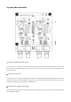
DIP-Switches 3/4 (high gain and filter before the output stage)
1 2 3
On High Gain (+10dB)
23Hz 30Hz
Off 0dB
- -
Without this filter the lower corner frequency here is roughly 7Hz. If both filters are activated the corner frequency is
approximately 47Hz.
DIP-Switches 5/6 (filter after the output stage)
1 2
On 27Hz 15Hz
Of - -
Without this filter the lower corner frequency here is roughly 0,3HzHz. If both filters are activated the corner frequency is
approximately 42Hz.