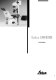
Leica DM IRB Instructions
Issued in 1998 by: Leica Microsystems Wetzlar GmbH Ernst-Leitz-Strasse D-35578 Wetzlar (Germany) Responsible for contents: Marketing MQM, product management, Tel.
Leica DM IRB Instructions 3
Copyrights All rights to this documentation and the software it describes are owned by Leica Microsystems Wetzlar GmbH. Copying of text and illustrations – in full or in part – by printing, photostat, microfilm or other techniques, including electronic systems, is only permitted subject to the express written consent of Leica Microsystems Wetzlar GmbH. The information contained in the following documentation represents the latest stage of technology and knowledge.
Contents Important notes on this manual ....................... 7 General safety information ............................... 8 Intended application .......................................... 10 The microscope and its components ............. Key subassemblies ............................................. Stands ................................................................... Tube mount ........................................................... Tube ...................................................
Contents Learn mode .......................................................... Installing the objective prisms ......................... Learning the IC objective prisms ..................... Installing the objectives .................................... Parfocality ............................................................ Dry objectives ...................................................... Oil immersion objectives ................................... Exiting the Learn mode ..............................
Important notes on this manual This manual is an integral part of the Leica DM IRB microscope and must be read carefully before you start using the microscope. The manual is multi-lingual. Due to the spiral binding you can turn the language version you want to the front. This manual contains important instructions and information on the operating safety and maintenance of the system. It must therefore be kept in a safe place.
General safety information This instrument of safety class 1 has been built and tested according to EN 61 010-1/IEC 1010-1/ VDE 0411-1, safety standards for electrical measurement, control and laboratory equipment. Make sure that only fuses of the specified type and rating are used as replacements. It is forbidden to use mended fuses or to shortcircuit the fuse holder. n. b.: n. b.: To keep the microscope in this safe condition, it is essential to note the advice and warnings given in this manual.
n. b.: The electric accessories of the microscope are not waterproof. If water gets inside them, it may cause electrical shock. Do not put the microscope and its accessories too near a water supply or anywhere else where water may get inside them. n. b.: Protect the microscope from major temperature fluctuations. These may lead to condensation which can damage the electric and optical components. n. b.: n. b.: Before changing fuses or lamps, always turn the mains switch off and disconnect the mains cable.
Intended application The new DM IRB is the logical further development of the successful inverted research microscope from Leica. It is used for examinations of cells and tissue, for micromanipulation and microinjection techniques all the way through to microdissection or confocal microscopy.
The microscope and its components Key subassemblies The following views of the whole microscope show and name important subassemblies of the microscope and its accessories. Fig.
The stand There are 5 basic versions of the DM IRB stand, which allow over 50 microscope variants to be configured. These 5 basic versions are: – Manual or electronic stand – With or without integrated fluorescence axis – With or without SLR front port or bottom port – Lateral photo port 100 % or 80 % – With or without integrated magnification changer The variants and their components, differences and uses will be explained individually in this manual.
Brightness adjustment Aperture diaphragm A 12 V 100 W transformer is built into the stand for stepless regulation of brightness with the brightness control. The aperture diaphragm determines the resolution, field depth and contrast of the microscope image. The best resolution is achieved when the apertures of the objectives and the condenser are roughly the same. Coarse and fine control The coarse and fine focus control allows fast and precise focusing of the microscope image.
Specimen stages and accessories Transmitted light illumination unit The specimen stage supports the specimens that are to be examined through the microscope. Several options are available to accommodate the wide variety of specimens examined, such as object guides, extension plates, specimen clips, scanning stage, heating stage, etc. The transmitted light illumination unit consists of the lamphousing and the transmitted light illumination column.
Installation site The microscope should be used in a dust-free room which is free of oil and chemical fumes and extreme humidity. Also, the workplace should not be exposed to major temperature fluctuations, direct sunlight or vibrations. These may impair measurements or photographs of the microscope image. Ambient conditions: Temperature Relative humidity n. b.: Lamphousings* and power units* must be placed at least 10 cm away from the wall and from flammable objects.
Unpacking Installation Please compare the delivery carefully with the packing note, delivery note or invoice. We strongly recommend that you keep a copy of these documents with the manual, so that you have information on the time and scope of the delivery later when ordering more equipment or when the microscope is serviced. Make sure that no small parts are left in the packing material. Some of our packing material has symbols indicating environment-friendly recycling.
Assembly Assembly tools Installation and assembly of the microscope should preferably be carried out together with a member of Leica sales or service staff. Only a few ordinary screwdrivers are required for assembly, and these are supplied with the microscope. Assembly of the transmitted light illumination column Wipe off the interface surface (4.3) with a dry cloth. Tilt the illumination column (4.1) slightly to the back and insert so that the pin (4.2) engages in the groove of the interface surface (4.
The lamphousing for transmitted light illumination for 12 V 100 W halogen lamps with single-lens aspherical collector and heat protection filter is an integral part of the transmitted light illumination column. The halogen lamp is preassembled. The chapter on Troubleshooting includes a description of how to assemble and change halogen lamps. The cable on the illumination column can then be connected to the 12 V 100 W socket on the back of the microscope stand. Fig.
Insert the light rings for Phaco (identified by the code numbers 0, 1, 2, 3 and the intercept distance S of the corresponding condenser top, e. g. 2 S1) and the DF diaphragm (identified by D for darkfield and the intercept distance S of the corresponding condenser top, e. g. D S1, see table “Technical Description”) in the slots of the disc as follows: – Slightly unscrew the two centring screws (10.11) using the supplied centring key (12.1).
5 1 6 4 3 Fig. 8 Condenser 0.53 S23 1 Condenser base, 2 Condenser top 0.53 S23 (interchangeable), 3 Condenser disc, 4 Aperture diaphragm, 5 Filter holder, 6 Dovetail guide 2 1 3 2 Fig. 9 Condenser tops for condenser base (8.1) 1 Condenser top 0.53 S23, 2 Condenser top 0.90 S1, 3 Condenser top P 1.40 OIL S1, 4 Spacer ring for assembling 9.2 and 9.3 4 6 Fig.
Assembly of IC condenser prisms The IC condenser prisms are assembled at the factory. The following steps are only necessary in case of a retrofit: Remove the condenser disc (11.5) by slackening the screw (11.4) on the underneath of the condenser. – Using the centring keys (12.1), slightly unscrew the two centring screws (10.11). – IC condenser prisms can only be inserted into the large holes of the condenser disc which have guide grooves (10.2). – Insert the IC condenser prisms in ascending order, e. g.
Condenser top The base and top of condenser 0.30 S70 form a self-contained unit (Fig. 6). The condenser top 0.30 S70 (13.4) cannot be used with the condenser base (8.1). The condenser top 0.53 S23 (8.2 and 9.1) is screwed straight on to the condenser base (8.1). A spacer ring (9.4 and 11.3) must be used for assembling the condenser tops 0.90 S1 and P 1.40 OIL S1 (9.2 and 9.3). Fig. 13 Assembly of condenser 0.
Condensers 0.53 S23 and 0.90 S1 With the illumination column tilted to the back, insert the condenser holder (15.4) into the dovetail guide of the illumination column from below (15.2). The condenser height adjustment should point to the left. Adjust the height of the condenser holder until its upper edge coincides with the condenser height marking S23 or S1 on the illumination column (16.1), depending on the condenser top used. Secure the condenser holder with the hexagonal screwdriver and clamp screw (15.
Assembly of field diaphragm Assembly of filters and filter holder To enable Koehler illumination when using condensers 0.53 S23 and 0.90 S1, a field diaphragm has to be assembled. Insert the field diaphragm module (18.1) into the mount (Fig. 18) from below. The diaphragm adjustment (18.2) should point in the direction of the tube. Secure with clamp screw (18.3). The Leica DM IRB is equipped with a holder with spaces for 3 filters with 40 mm diameter.
Assembling the ICT objective prisms Assembling the IC module and IC objective prisms The IC prism disc with the IC prisms ordered by the customer are already assembled in the microscope at the factory. In case you want to retrofit the IC prism disc, please proceed as follows: Remove the front cover (22.2) under the objective nosepiece (23.1) after slackening the Allen screws (22.4). Insert the IC prism disc (22.1) in the mount and tighten with the two Allen screws. n. b.
Inserting the analyser Prism D is the standard prism with greater shearing and therefore higher detection sensitivity for minute topological and refractive index variations in the specimen. Prism D1 has smaller shearing than prism D and a lower detection sensitivity for topological and refractive index variations. However, prism D1 is better at resolving details of fine specimen structures. Remove the blind slide and insert the analyser (24.2) from the left as far as the 1st clickstop. Fig.
Inserting the fluorescence module The fluorescence module (Fig. 26) is part of the fluorescence stand, but is also available as a retrofit kit. To retrofit the fluorescence module, remove the blind cover from the stand. The fluorescence module can be fitted with up to four different filter cubes (26.3). They are inserted into the dovetail mount (26.2) of the fluorescence module with their engraving facing downwards (towards the turret plate).
! 4. Connect the lamp plug to the connecting socket in the stand (28.3). 5. Insert light filters, 50 mm Ø into the 2 spaces in the lamphousing mounts (29.4). Connect the appliance cable to the mains socket on the microscope stand (28.4)! Fig. 28 Back view of microscope 1 Space for assembling a lamphousing mount or mirror housing, 2 Hole for guide pin, 3 Socket for lamp plug, 4 Mains socket, 5 Potential equalisation Fig.
Assembling and exchanging incident light lamps Exchanging the 12 V 100 W halogen lamp: n. b.: Lamphousing 107 L Slacken the fixing screw on the cover and lift off the cover (Fig. 32a and 32b). Move the collector to the front and pull the defect 12 V 100 W lamp out of the base towards the front. Without removing its protective cover, put a new lamp into the base, without tilting, as far as it will go. Disconnect the lamp and lamphousing from the power supply. Pull out the mains plug. n. b.
Lamphousing 106 z L Slacken the fixing screw on the lid (33.10). Pull the cut-out plug slightly out of the socket and flip up lid (33.11; 33.1). Move the collector to the front and lift the defect lamp out of the base (33.1; 33.2; 33.3). For convenience, the lamp holder can be removed from the lamphousing as well. To do this, slacken the fixing screws on the lamp holder (33.10) and pull out lamp holder (Fig. 34).
Assembling and exchanging incident light lamps Assembling and exchanging Hg and Xe lamps Power units: Hg and Xe lamps are powered by separate power units. Please make sure to read the special manuals for these power units. Lamphousing 106 z L Besides the halogen lamp, the following gas discharge lamps can be used, which each require different lamp holders (Fig.
Always insert the burner so that n. b.: n. b.: It is extremely important to heed the following advice! Always disconnect the power unit from the mains before assembling the lamphousing 106 z. Wait for the lamphousing to cool down for at least 15 minutes as otherwise it may explode. Never touch glass parts of the burner with your bare hands as finger perspiration burns in. Wipe off any finger perspiration and dirt with a clean cloth. Adjust the lamps immediately after ignition.
Move the collector to the front position with the focusing knob (36.1). n. b.: Remove the protective cover from the burner. Put the lamp holder with burner inserted into the lamphousing and secure with the screws (10.10). Try moving the collector (36.1): it must not touch the power lead. When closing the lamphousing, make sure that the pins of the cutout plug engage in the sockets (35.11). Retighten the screws of the lid. Push the cut-out plug in as far as it will go.
! n. b.: Hold on to the tube adapter until the clamp screw is tightened. Then insert the HC FSA 25 PE tube in the change mount of the tube adapter and fasten with clamp screw. The following tubes from the Leica DM R range are also adaptable: Bino HC BSA 25 (42.1) Trino HC FSA 25 P and PR (42.2) (P + PR = with and without back reflection) Photo port for 1 photo/TV connection (43.2) Photo port for 2 photo/TV connections (43.1) Switchable 100 %/100 % (25.
Fig. 41 Tubes from the DM R range 1 HC FSA 25 PE, 2 Side port for optical overlay, 3 Tube adapter IR HC, 4 Clamp screw for mounting the adapter to the stand, 5 Clamp screw for mounting the tube to the adapter, 6 Photo/TV port Fig. 40 1 Tube adapter R/IR HC, 2 Clamp screw 6 1 2 2 5 1 3 4 Fig.
Adaption of the slide overlay device and the macro dual system With the Leica DM IRB inverted microscope, the slide overlay and macro devices can only be adapted onto the FSA 25 PE tube. This tube has a side flange (44.1) for mounting the reflection optics. These reflection optics are used for mechanical and optical adaption of the slide overlay device and the macro dual zoom system. The slide overlay device consists of the reflection optics (44.2), the illumination unit with 6 V 4 W halogen lamp (44.
Screw the reflection optics (46.3) to the tube flange with the coupling ring (46.2). Align the macro adapter (46.5) to the macro dual zoom and secure with the screw ring (46.6). Screw the macro adapter and macro dual zoom to the reflection optics with the coupling ring. Check that the guide pin engages in the groove. ! Important! Be very careful to keep the optical surfaces clean. Any dust particles and finger marks will show up in the image. The graticule diameter for all HC PLAN eyepieces is 26 mm.
Inserting the photoeyepieces* The HC PLAN observation eyepieces (slot-in diameter 30 mm) are designed for direct visual observation. For the adaption of photo-micrographic equipment with a fixed magnification factor, e. g. DM LD and MPS systems, and for special TV adaption systems, special eyepieces with a slot-in diameter of 27 mm and the engraving HC...PHOTO are used (note the adapter!) See special manual for further details on adapting photo and video equipment.
3-plate x/y stage To assemble the square insert plate: The 3-plate x/y stage no. 19, size 247 x 230 mm, x-y adjustment range 60 x 40 mm, is delivered in separate packaging and assembled as follows: This stage is usually delivered with the DM IRM, so the description of its assembly has been taken from the DM IRM manual! 1. Screw the 3 Allen screws out of the stage support surfaces and wipe any remains of packaging or dust, etc. from the stage with a clean cloth. 2. Align the stage with the x-y drive (49.
Rotary stage and insert frame for coverslips Connecting the microscope to the mains The rotary stage is secured with 3 screws. The rotary mount has to be moved to make all the screw holes accessible. Align the screws (51.2). When you have installed all the components as described, you can connect the microscope to the power supply with the mains cable. ! n. b.: Washers (51.3) should be used as well for the back drill holes.
The E version DM IRB/E The Leica DM IRB/E offers the following additional functions: For users who want to program the Leica DM IRB/E microscope themselves, a free software development kit called “Leica SDK“ is available for Windows 3.11, Windows 95 and Windows NT on request. – – – – Important note: Before using a brand new Leica DM IRB/E microscope for the first time, an initial installation has to be carried out.
Assembly and initial installation The assembly of the individual components, such as transmitted light illumination column, condenser, etc. has been completed. If necessary, delete them by sustaining the relevant keys (␣ ␣ ␣ ␣ , Fig. 53b) for longer than 1 sec. Using the lower focus key, behind the handwheel on the right, move the nosepiece to the lower stop. n. b.: The objectives should not be screwed in at this point. The best time to do this is when executing the learn mode.
Learn mode 0 µm S1 10 0xPH3 ↔ After switching on, the microscope is in the normal operation mode. l Normal operation mode The learn mode is switched on with the “LEARN” key. The objective nosepiece rotates through 180° so that the current objective is in the most accessible position (furthest to the right on the outside). This function also serves for cleaning, assembling, immersing, etc. the objective. Lea rn: EXIT PARF OB J L / R - > The “EXIT” option in the display flashes.
Installing the objectives Select the “Objectives” option in the Learn mode (OBJ) by pressing the “CHANGE” key; the “OBJ” option now flashes. Confirm your choice with the “LEARN” key. ↔ Turn the IC turret (situated under the objective nosepiece) until it clicks into the brightfield position (H). Operate the focus handwheel until the letter H appears on the display panel as well. Turn the IC turret by a quarter of a rotation into the next clickstop area. The message “IC prism 2” appears in the display.
Display: Objective magnification By turning the focus handwheel, select the number in the electronic display that corresponds to the magnification of the objective. ↔ Display: Phase contrast By pressing the “CHANGE” key, select the display field for phase contrast. Ob j e c t i v e 1 : 5x PHO EX I T Learn mode: Objective data – Phase contrast Display: IC objective prism By pressing the “CHANGE” key, select the display field for the IC objective prism.
Operating modes: Dry/Immersion To ensure simple yet safe objective change, the objectives have to be classified in one of the following three categories: 1. Dry objectives (D) = all dry objectives with a short working distance (< = 3 mm). 2. Immersion objectives (I). 3. Combined objectives (C) = dry objectives with a long free working distance (> 3 mm), objectives which can be used for scanning purposes as well through an oil layer.
Parfocality Oil immersion objectives Select the “Parfocality” option (“PARF”) in the Learn mode by pressing the “CHANGE” key; the “PARF” option now flashes. Confirm your choice with the “LEARN” key. Once the parfocality has been learnt for all the dry objectives it can be done for the immersion objectives. Please remember that if the specimen is very small and lightweight it must be fixed onto the stage to prevent it being moved by the adhesive force of the oil.
Individual user adjustments Select the option “L/R” in the Learn mode by pressing the “CHANGE” key and confirm your choice by pressing the “LEARN” key. ↔ Sw i t c he s : EX I T Ob j ec t . <> Foc us Learn mode: User adjustment This option allows you to choose whether you want to operate the objective nosepiece on the left or the right side of the microscope. The function of the focus keys then also shifts to the other side of the microscope.
Installing the fluorescence filter cube Select the “FLUO” option in the Learn mode by pressing the “CHANGE” key. Confirm by pressing the “LEARN” key. F i l t erb l ock 1: I3 EX I T Learn mode: Fluorescence Pull out the filter cube drawer on the left side of the microscope stand and put the filter cube you want to use in the holder of the fluorescence turret plate in the light path. The filter cube must click noticeably in position.
Motorized objective nosepiece The electronic nosepiece control allows easy and safe change of the objective magnification. Objectives are changed with 2 push buttons (objective changing keys) which are easily accessed behind the focusing handwheel on the left of the microscope. The upper key is pressed to increase the magnification, the lower key to decrease the magnification. Short pressure on the key switches to the next lower or higher magnification. If you sustain the key for longer then 0.3 sec.
Operating modes DRY and IMMERSION The Leica DM IRB microscope is equipped with a switch function between the operating modes “Dry” and “Immmersion” (IMM) to ensure straightforward, error-free operation. This prevents – dry objectives from being immersed in oil by mistake – immersion objectives from being used without immersion oil by mistake.
The procedure for switching to the Dry mode is analogous: Again, press the keys “lower z position” and “focus position” on the control panel of the microscope simultaneously to switch from “Immersion” to “Dry”. The objective nosepiece is lowered and the message “Change Objective” appears in the display. You now have the opportunity to put a new specimen slide (without immersion oil) on the stage.
Brightness adjustment Instead of a potentiometer, Leica DM IRB/E microscopes are equipped with an incremental transducer for brightness adjustment. This means that the adjustment wheel is automatically moved from clickstop to clickstop and therefore has no end stops. After it is switched on, the microscope is in normal operating mode. In the first line of the LC display, the current Z position is given in µm or mm on the left.
Electronic focus The electronic focus offers the user the following advantages: – Extremely sensitive focusing, especially for high magnifications. – Fine focusing selectable in 4 steps; coarse focusing can be switched on “blind” at any time. The stepwidths desired by the user (corresponding to gear ratio and sensitivity) are allocated to every single objective and automatically reset as soon as the particular objective is used.
– Key for defining the “lower Z position”. Pressing the key for longer than 1 sec. deletes the threshold; another press of the key for longer than 1 sec. sets the current Z position as “lower threshold”. for defining the “upper Z threshold” – Key (= focus position). Pressing the key for longer than 1 sec. deletes the threshold, another press of the key for longer than 1 sec. sets the current Z position as “upper Z threshold”.
Motorised fluorescence filter cube change (option) Three keys are used for operation: A control panel is connected to the Leica DM IRB for motorised filter cube change. Mot. filter cube module Shutter filter module RS 232 control F-bus panel Back of Leica DM IRB F-bus F-bus in out Mains unit Control panel for mot. filter cube change Connection for motorised fluorescence filter cube change The two “FLUOR” keys are used to switch to the adjacent filter cube.
Control unit* An electronic control unit can be connected for the remote control of individual microscope components such as objective nosepiece and Z drive. It is operated with keys on the front of the control unit. The control unit can also be combined with a dual footswitch. Connecting the control unit The connection port is on the back of the unit. When using a Leica DM IRB microscope, the unit must be powered by an external power unit.
Keys on the control unit The control unit is operated by keys.
The control unit is operated in a similar way to the key-mode operation of the Leica DM IRB microscope. Significance of individual keys: This is also the reason why the nosepiece rotation is slightly delayed after the keys are pressed. The LAST key is used to switch to the objective that was used last. LAMP FLUOR Brightness can be adjusted with the arrow keys: Up arrow → brighter, down arrow → darker. The ON/OFF key is used to switch the lamp off and on.
FOCUS X-Y Here the arrow keys control the movement of the Z drive. The movement speed for the fine focusing is selected with the STEP key. For safety reasons, the movement range is limited to 400 µm above the focus position and 400 µm below the lower Z position. If both arrow keys are pressed at the same time, the system switches to coarse focusing (SC). The Z drive then moves at a higher speed.
Examples for the use of the footswitches Example 1 Switching between two magnifications with a footswitch: Set a magnification and switch to a second magnification you would like to use. Assign the LAST function for magnification change to the left, by first pressing key 1 and then the LAST key (at MAG). Now switch between the two magnifications with the left footswitch.
Person sensor (option) Switch position AUTO The dark flap can be opened automatically via a sensor when you look through the microscope and closed again when you look away. This is achieved by mounting the person sensor (order no. 505 101) onto the right eyepiece tube and connecting the cable on the sensor to the SHUTTER socket on the control unit for motorised filter cube change. The dark flap is opened when you look through the eyepiece.
Front controls There is an LC display and five control keys on the front of the microscope. lower Z position set Z position focus keys on the right side of the microscope stepwidth - 1 . 86mm S 1 10 0 xPH 3 HH Objective data current IC prism or brightfield focus position set D fluo cube operating mode dry/imm LC display – Z position in µm or mm. – Set stepwidth for the fine focusing (S0, S1, S2, S3 and coarse focusing = SC, can be switched on and off by simultaneously pressing both focus keys).
Operation Basic setting for transmitted light n. b.: Switching on the halogen lamp When using acids or other aggressive chemicals, special care should be taken. Avoid direct contact of these substances with optical and mechanical components. Switch on the 12 V 100 W lamp at the mains switch (55.7). Adjust the brightness with the dial. The numbers are not absolute parameters, but merely serve for reproducible setting. The white dot on the dial indicates the setting for approx.
Adjustment specimen For initial microscope adjustment we recommend you use a specimen that has both high and low contrast areas. It is easier to focus incident light fluorescence specimens in transmitted light first. Focusing the specimen (For the DM IRB version, please read the section about the operation of the E focus and objective nosepiece first. Here, an example of manual operation is given for each case.) Focus the specimen you want to examine.
Checking of various microscope components Operation of L objectives with correction mount Engage or disengage the filters (54.16) according to the required brightness. If necessary, disengage the Bertrand lens by turning the knurled knob (54.22), pos. 1. Disengage the analyser (55.21), if necessary, by pulling it out partway. Disengage the filter systems, if necessary, by rotating the turret (55.11). Push in the switch rod(s) for the beamsplitter (54.23).
Binocular tube HCI B22 or HCI BV22 For eyepieces with inserted graticule only*: ● Greatly defocus the specimen or remove from the light path. ● Exactly focus the graticule by adjusting the eyelens with a relaxed eye (the eye relaxes best if you look out the window at a distant object for a moment). ● Focus the specimen, only adjusting the eyepiece with graticule. ● Then close this eye and focus the specimen by adjusting the second eyepiece only.
To correct defective eyesight: ● Look through the right-hand eyepiece tube with your right eye and sharply focus the specimen with the fine drive. ● Then look at the same area of the specimen with your left eye and rotate the left eyepiece tube until you obtain a sharp image. Do not use the fine drive for this. ● If using eyepieces with adjustable eyelenses, do not compensate for defective eyesight by adjusting the eyepiece tube, but by adjusting the eyelens of the eyepiece. Fig.
Operation of the side photo/TV port Operation of the front photo/TV port The delivery comprises two alternative outfits for the lateral photo/TV exit (Fig. 59a). Stands either with or without SLR front port can be supplied. One outfit has a beam split of 1 100% visual 80 % side 2 120 % visual 80 % side The beam split is as follows: The second version has a beam split of 1 100 % visual 110 % side 2 110 % visual 100 % side The side port is switched off, i. e.
Operation of objectives ! Immersion objectives OIL: Only use DIN/ISO standard immersion oil. n. b.: Observe the safety information on the immersion oil! W: Water immersion. The special water immersion objectives with ceramic front part can be used for all hydrous solutions. IMM: Universal objective for water, glycerine and oil. Colour coding of objectives → “Technical data”. Locking objectives Some immersion objectives (with knurled grip) can be locked in a shorter position.
Operation of transmitted light Brightfield illumination Setting the aperture diaphragm Illumination techniques where the empty areas of the specimen are the brightest parts are called brightfield. Absorbing specimen structures are required for brightfield imaging, i. e. most specimens will need staining. Alternatives are optical contrasting techniques such as phase or modulation contrast. The aperture diaphragm determines the lateral resolution, field depth and contrast of the microscope image.
Setting Koehler illumination Turn a 10x objective into the light path and focus the specimen. – Engage the condenser disc into the “H” = Hellfeld = brightfield position if necessary. – Close the field diaphragm. – Adjust the height of the condenser until the edge of the field diaphragm is sharply in focus and also: Centre the image of the field diaphragm in the middle of the field of view with the two centring screws. Open the field diaphragm until it just disappears from the field of view.
Visual comparison of the objective and condenser apertures is done as follows: remove an eyepiece from the eyepiece tube, or engage the Bertrand lens by turning the knurled wheel (62.11), (pos. B) and focus with the lever (62.11). Close or open the aperture diaphragm until the image just shows up in the pupil (= brighter circle) of the objective. This is regarded as the standard setting, i. e. condenser aperture = objective aperture. Replace the eyepiece or disengage the Bertrand lens.
Operation of phase contrast Phase contrast observation Like transmitted light darkfield and transmitted light interference contrast, phase contrast is used to produce high-contrast images of unstained specimens. Setting phase contrast with condenser 0.30 S70 Phase contrast observation is possible with objective magnifications from 5x to 40x. Turn a phase contrast objective (engraving e. g. PH2) of the lowest magnification into the light path and focus the specimen.
Setting phase contrast with condensers 0.53 S23 and 0.90 S1 Phase contrast observation is possible with condenser 0.53 S23 with objective magnifications from 5x to 100x, with condenser 0.90 S1 from 10x to 100x. For both condensers, phase contrast is set as described as for the 0.30 S70 condenser. However, before the centration process itself, correct Koehler illumination must be set.
Operation of transmitted light darkfield Darkfield observation Darkfield observation is not possible with condenser 0.30 S70, with condenser 0.53 S23 it is possible from 5x objective magnification, the max. usable objective aperture is 0.40. With condenser 0.90 S1, DF observation is possible from objective magnification 10x, the max. usable objective aperture is 0.75. Objectives with higher apertures can be used if it is possible to reduce the aperture with a builtin iris diaphragm.
Operation of transmitted light polarisation DL polarisation Polarisation contrast for examining birefringent specimens is possible with condenser 0.30 S70 with objective magnifications from 2.5x to 40x, with condensers 0.53 S23 or 0.90 S1 from 5x or 10x to 100x. A P 1.40 OIL S1 condenser top is also available for extremely hgh resolution. Crossing the polarisers First: Set Koehler illumination.
Operation of transmitted light interference contrast TL interference contrast TL interference contrast observation is possible with condenser 0.30 S70 with objective magnifications from 10x to 40x, with condensers 0.53 S23 or 0.90 S1 from 10x to 100x. For objective 100x there is also a condenser top P 1.40 OIL S1 for extremely high resolution.
Centration of the condenser prisms Objectives for ICT If you have ordered a complete microscope, this adjustment will already have been made at the factory. However, it is advisable to check the centration from time to time, particularly after transport: disengage the objective-side IC prisms (pos. H). Transmitted light interference contrast is possible with the brightfield and phase contrast objectives which have the code letter of the pupil position in the first line of engraving, e. g.
Choice of prisms Choose the objective-side prism with the letter indicated in the top line of the objective engraving, e. g. C for pupil position C, by rotating the turret. Choose the condenser-side prism that corresponds to the magnification of the objective used, e. g. pos. 40 for objective 40x, by rotating the disc. Setting ICT contrast Turn the objective-side prism turret to the left and right (Fig. 67). Also adjust the contrast with the aperture diaphragm.
Operation of incident light fluorescence n. b.: Only with microscope with integrated incident light fluorescence axis. The BG 38 filter should always be used for photography. When not looking through the microscope, always block the incident light path to prevent specimens fading. Push the switch rod in all the way. Fluorescence observation Focus the specimen in transmitted light first, if possible (perhaps Phaco or ICT).
Centration of the 12 V 100 W, Hg, Xe lamps Lamphousing 107/2 for 12 V 100 W halogen lamp This lamphousing is permanently set and does not require centration. However, it is essential that the lamp is aligned straight in its mount. Lamphousing 107 L for 12 V 100 W halogen lamp (Fig. 68) 3 alternative centration methods: Method 1: Centration with a centring aid On the right side of the microscope there is an adjustment window showing an image of the light source.
5. Using an Allen key, adjust the screw for horizontal adjustment (68.3) until the pale stripe of the filament image is in the centre of the pupil. 6. Then adjust the screw for vertical adjustment (68.2) to align the filament image vertically in the centre of the pupil. Method 3: Centration in the plane of the specimen stage 1. Put a piece of paper or non-shiny piece of Leica packaging on the specimen stage and roughly focus the surface with a low-magnification objective. 2.
Hg 100 W and Xe 75 W lamps n. b.: Never look straight into the light path! Remember the risk of glare when switching to the BF or Smith reflector! Centration of Xe or Hg gas discharge lamps Move the reflection of the discharge arc to the side or entirely out of the light path by adjusting the centring screws on the back of the lamphousing (70.2, 70.3, 70.4). Focus the direct image of the arc with the collector adjustment (70.6).
Fig.
Centring the aperture diaphragm Centring the field diaphragm Turn a low to medium objective magnification 10x/20x into the light path and focus a specimen with the coarse and fine drive. Turn a low to medium objective magnification 10x/20x into the light path and focus a specimen with the coarse and fine drive. Open the field diaphragm almost as far as the edge of the field of view. Using the centring buttons (72.4), centre the field diaphragm to the edge of the field of view.
Possible errors Weak fluorescence, insufficient brightness: Wrongly stored, overaged or faded specimens. Fast fading of the specimens (e. g. for FITC). Unspecified filter combination. Numerical aperture of the objective too low. Low-contrast image due to: Excitation bandwidth too wide. Inspecific staining. Fluorescing mounting medium. Autofluorescence of objective or immersion oil. Glass surfaces dirty. Eyepiece magnification too high. Spent lamp. Room too bright.
Operation of filters Light filters Up to max. 3 light filters can be inserted in the filter holder (1.16). They can be switched in and out the light path as required. Filter Use Grey filter Grey filters (neutral density filters) are used to attenuate the light without influencing the colour temperature. The engraved value, e. g. N16, indicates the attentuation value. So N16 means reduction to 1/16 = 6.3 % transmission.
Operation of the slide overlay device Slide overlay device The slide overlay device is used for reflecting measurement and comparison patterns, µm marks, marker arrow, company logo and quality data etc. into the microscope image so they appear on the photograph. Slides with the following line patterns are available: Marker arrow Measurement scale 10 mm = 100 divisions µm marks for 2.
Operation of the macro device Like the slide overlay device, the macro overlay (Fig. 73) only works in the 50/50 beamsplitter position (switch rod in middle position) of the FSA 25 PE tube. The microscope illumination is left switched off to avoid disturbing image brightening. The object is placed on the stage under the mirror housing of the macrodual zoom (73.11) and illuminated. Fig.
The total magnification in the microscope, the reproduction ratio on the photograph or TV image can be quickly and easily measured with a scale and calculated. n.b.: For normal viewing without the macro mirrorhousing or macrodual zoom, put on the cover to avoid disturbing overlay effects. The mirror housing (73.11) can be rotated through 360°, for example to alter the angle at which the photograph is taken. This is done by loosening the Allen screw.
The total magnification can be roughly calculated with the scale divisions on the macrodual zoom: The following factors have to be multiplied for this: – Magnification factor of the working distance (scale (73.9), e. g. 0.11x) – Zoom factor (scale (73.8), e. g. 1x) – Correction factor of the reflection optics (without engraving 1.17x) – Eyepiece magnification (e. g. 10x) e. g. 0.11 x 1 x 1.17 x 10 = 1.29 The total magnification in the eyepiece would therefore be 1.29x.
Length measurements The following components are required for length measurements: – Graticule with scale in eyepiece (Fig. 76) or in the slide overlay device (Fig. 74). – Transmitted light stage micrometer for calibration. Before measurement, the micrometer value of the objective/eyepiece combination must be known, i. e. the distance in the specimen that corresponds to a scale interval in the graticule you are using.
Various adapters are available for connecting TV cameras with c-mount or B-mount objective thread: Recorded picture diagonal in mm with 1 1 /3 inch /2 inch /3 inch camera camera camera 2 1 inch camera Without zoom magnification, for 1 chip cameras c-mount adapter 1x HC 16 c-mount adapter 0.63x HC+) ␣– c-mount adapter 0.5x HC ␣– c-mount adapter 0.35x HC ␣– c-mount adapter 4x HC+) ␣ ␣4 11 17.5 ␣␣– ␣␣– ␣ 2.8 Without zoom magnification, for 1␣ –␣ 3 chip cameras each in connection with 0.
Calculation of the magnification on the monitor For all TV exits the magnification on the monitor can be calculated with the following formula: MTV = objective magnification x tube factor x monitor diameter TV –––––––––––––––––––– adapter magnification x chip diameter of camera Beamsplitting for photomicrography or TV microscopy DM IRB with side photo port only and correspondingly with one beamsplitter switch rod (81.1).
n. b.: Long-term video microscopy The solid and therefore stable basic body of the stand takes a while to stabilise thermally after the microscope is switched on. For investigations taking over > 30 min. therefore, the microscope should be switched on about 1␣ – 2 hours beforehand. Fig.␣ 80␣ ␣ Leica DM IRB, equipped with three TV cameras Fig.␣ 81␣ ␣ Switch rods for beamsplitting 1 Upper beamsplitter switch rod (SIDE), 2 Lower beamsplitter switch rod (FRONT) 1 2 Fig.
Operation of LMC Leica modulation contrast (LMC) is a special form of oblique illumination based on the principle of Hoffmann modulation contrast. In this technique, the phase gradients of an unstained specimen are converted into differences in amplitude with the aid of a modulator. This gives a three-dimensional impression similar to an interference contrast image. Unlike interference contrast, however, the specimen can be observed through birefringent plastic materials such as petri dishes.
Principle of LMC The principle Leica modulation contrast (LMC) is based on the principle of Hoffmann modulation contrast. This imaging technique is particularly suitable for unstained, colourless objects with little image contrast. Such objects change the phase of the light when it passes through them. The conversion of these phase gradients into differences in amplitude results in a three-dimensional image similar to that of differential interference contrast.
Components The components LMC objectives LMC consists of the following components: The following objectives are available: S40/0.50 LMC condenser The condenser (order no. 521 225) is supplied with a condenser disc to accommodate 3 LMC diaphragms, plus two phase contrast light rings and a brightfield position (3x LMC, PH1, PH2, brightfield). Adhesive labels are enclosed for labelling the individual positions.
Assembly/adjustment Assembly Adjustment When taking the following steps, consult the manual for the Leica DM IRB/E manual. Open the aperture diaphragm on the condenser fully. ! n. b.: Before installing the LMC components, remove the field diaphragm. Also remove any filters, prisms and interference contrast components. Screw the LMC objectives into the objective nosepiece. Replace the condenser on the microscope with the S40/0.50 LMC condenser.
The light slit diaphragm is now adjusted until the bright stripe of the slit image is fully inside the grey stripe of the modulator. The light slit diaphragm can be rotated and moved in x and y direction. For the 10x objective the image of the modulator and the light slit are virtually the same size. Adjust the light slit diaphragm until the bright slit lies near the dark edge. Always make sure that the objective name and the name of the light slit diaphragm coincide.
Areas of application On the Leica DM IRB/E microscope, LMC is particularly suitable for life science applications. Use of birefingent materials Transparent, living cultures in petri dishes can be observed in three dimensions, for example. Use of a micromanipulator The long free working distance of the S40/0.50 LMC condenser offers plenty of space for manipulation tools. The 3D image impression makes it easier to find suitable injection points. Optical sectioning LMC produces a large, flat observation area.
Care and maintenance Cleaning of lacquered components n. b.: Before cleaning and maintenance work, remember to disconnect from the mains! Protect electric components from damp! Microscopes in warm and humid climates need special care to keep them free of fungus. The microscope should be cleaned every time it is used and the microscope optics should be kept immaculately clean. Dust and loose particles of dirt can be removed with a soft brush or lint-free cotton cloth.
Obstinate dirt on glass surfaces can be carefully removed with a clean cloth moistened with distilled water. If the dirt can still not be removed, pure alcohol, chloroform or benzine can be used instead of distilled water. Cleaning objectives n. b.: Objectives should not be screwed apart for cleaning. If there are signs of interior damage, send the objectives to your nearest Leica agency for repair. We also advise against cleaning the inner surfaces of eyepieces.
Troubleshooting All Leica instruments are manufactured and tested with extreme care. If you do have cause for complaint, however, please do not try to repair the instruments and their accessories yourself. Contact your national agency or our central servicing department, the Technical Service in Wetzlar, direct. Postal address: Leica Microsystems Wetzlar GmbH Abt. Technischer Service Postfach 20 40 D-35530 Wetzlar Tel. (0) 64 41-29 28 49 Fax (0) 64 41-29 22 66 Apart from preparation errors (e. g.
Replacing the 12 V/100 W halogen lamp n. b.: Remember to disconnect from the mains! Leave the protective cover on until the lamp is inserted. Avoid making fingermarks, or wipe off immediately. ● Switch off the microscope and the power unit (if used). ● Disconnect the appliance cable of the microscope and the power unit. ● Disconnect the transmitted light illumination column from the power supply on the back of the microscope. ● Screw off the lamphousing with a 3 mm Allen key. ● Remove the faulty lamp.
Replacing the mains fuse on the power unit* n. b.: Remember to disconnect from the mains! ● Switch off the microscope and the power unit. ● Disconnect the appliance cable of the microscope and the power unit. ● Remove the defect fuse from the fuse holder. Replacement fuses of IEC 127-2 standard and/or UL 198 G and/or company type: Part no.: Name: 846-205.000-00 T4A Wickmann 19 195/ Schutter FST Fig. 85 Lamphousing 107/2 1 Screw for opening the lamphousing 1 Fig.
n. b.: n. b.: Never use fuses with a different rating from the ones specified. ● Connect the microscope and the power unit to the mains. Replacing the 12 V / 100 W halogen lamp in lamphousing 106, 107, 107/2 Ask a member of Leica field staff to show you how to change the halogen lamp properly. Here again are all the necessary steps: Always disconnect external transformers and the microscope from the mains when carrying out assembly work! ● Switch off the microscope and the power unit.
n. b.: Leave the protective cover on until the lamp is inserted. Avoid making fingermarks, or wipe off immediately. ● Remove the defect lamp. ● Put a new 12 V 100 W halogen lamp into the lamp holder without tilting (86.2 or 87.2). ● Move the collector back. ● Put on the lid and secure with screw (85.1 or 87.1). ● Align the lamphousing against the microscope and secure with the clamp screw. ● Connect the lamphousing to the power unit. Replacing the 12 V 100 W halogen lamp in lamphousing 106 z* n. b.
Changing the Hg and Xe lamps on lamphousing 106 z n. b.: ● Always disconnect the power unit from the mains before carrying out assembly work. ● Wait for the lamphousing to cool down for at least 15 minutes as otherwise it may explode. ● Never touch glass parts of the burner with your bare hands as finger perspiration burns in. ● Wipe off any finger perspiration and dirt carefully (perhaps using alcohol). ● Adjust the lamps immediately after ignition.
● Put the lamp holder with burner inserted into the lamphousing and secure with the screws (90.10). ● Close the lid of the lamphousing. When closing the lamphousing, make sure that the pins of the cut-out plug engage in the sockets. ● Retighten the screws of the lid. ● Push the cut-out plug in as far as it will go. ● Align the lamphousing against the microscope and secure with the clamp screw. ● Connect the lamphousing to the power unit (compare mains voltage!). Fig.
Storage Packaging and transport Protect your microscope from dust by putting on the cover after each work session. The original packaging should be used if the microscope has to be dispatched or transported. Also, the delivery note with full details should be enclosed. The microscope must be kept in a cupboard in which the temperature is ≥ 5°C above room temperature. The cupboard must have ventilation holes which are plugged with cotton wool, for example, to keep dust out.
Technical description All techniques, not only in microscopy, are subject to limits of performance due to basic physical laws and principles of eye physiology. The following information should therefore be remembered when using the microscope. Objective lettering Examples and explanation of symbols: ∞/C PLAN 10x/0.22 ∞ / 0.17 C PLAN 40x/0.65 Performance data of objectives The Leica DM IRB microscope is based on tube length ∞ (infinity) and a focal length of the tube lens of f = 200 mm.
D (or A, B, C) Pupil position of objective (important, e. g. for IMC integrated modulation contrast). Objective type (performance class): C Plan Achromatic objective with particularly good price/performance ratio. Field performance max. 20 mm. N Plan Achromatic objective with increased field performance of at least 20 mm. PL FLUOTAR ® Semiapochromats with particularly good field performance of at least 25 mm and chromatic correction. Universal optics for all techniques.
Colour coding of the objectives The magnification of each objective is indicated as per DIN/ISO standard by a colour ring: 100x 125x 150x 160x 63x 40x 50x 25x 32x 16x 20x 10x 6.3x 4x 5x 2.5x 1.
Performance data of eyepieces Leica eyepiece type Magnification/ fov HC PLAN HC PLAN HC PLAN HC PLAN HC PLAN HC PLAN 10x/20 10x/20 12.5x/16 10x/20 10x/22 11x/20 Eyepiece port +) M M MF M MF Eyepiece tube diameter: 30 mm +) M MF = With removable or push-back anti-glare protection for use with or without eyeglasses. = Ajustable eyelens (dioptre compensation) and slot for graticules of 26 mm diameter. = With illuminated graticule.
Example: Eyepiece 10x/20 Objective PLAN 4/0.10 Magnification factor 1x Your Leica agency can supply you with a constantly updated data sheet on all Leica objectives. Eyepiece graticules Total magnification 10 x 4 x 1 = 40x Graticules for length measurements and grain and particle measurements Field performance of objectives The field performance of objectives is not engraved on the objectives. It may vary within the same class, e. g.
Filter performance data Filter Use Grey/neutral density filter N Grey (neutral density) filters are used for light attenuation without influencing the colour temperature. The engraved value, e. g. N16, indicates the attenuation value. So N16 means a reduction to 1/16 = 100/16 = 6.25 % transmission. Green filter, GR, panchromatic For general contrast enhancement and blackand-white photography.
Tube performance data Binocular tube HCI B22 Tube changing is the same as for the upright microscopes. The tubes are interchangeable. The binocular tube consists of a basic part with the tube change ring at the bottom. The tube lens has the factor 1x. The Siedentopf binocular part allows adjustment of the interpupillary distance from 55 mm to 75 mm. The viewing angle is 45°. The tube has adjustable eyepiece tubes for mechanical compensation of the tube length when the interpupillary distance changes.
Trinocular tube HCI 3T22 HC FSA 25 PR The trinocular tube consists of a basic part with the tube change ring at the bottom, the tube lens has the factor 1x. The Siedentopf binocular part allows adjustment of the interpupillary distance from 55 mm to 75 mm. The viewing angle is 45°. The tube has adjustable eyepiece tubes for mechanical compensation of the tube length when the interpupillary distance changes. It allows a field of view index of 22. The documentation port is only operated with HC components.
HC FSA 25 PE Condenser performance data Binocular observation and photo tube, viewing angle 30°, with provision for optical overlay for documentation of transparencies (slide overlay device) or opaque macro objects (macro device). Condenser 0.
Together with condenser top 0.53 S23, max. FWD 30 mm, culture vessels can be examined microscopically up to liquid levels of 25 mm. For contrasting techniques brightfield (HF), phase contrast (Phaco/PH), transmitted light interference contrast (ICT) and polarisation contrast, objectives with magnifications up to 100x can be used. For transmitted light darkfield we recommend objectives with a numerical aperture up to 0.40. For condenser top 0. 90 S1, max.
Stages Plane stage and mountable object guide The plane stage is secured to the microscope with 3 screws. The object guide can be mounted to either the right or the left of the plane stage. 3-plate x/y stage To attach the stage, 3 screw holes first have to be accessed by moving the stage in x/y direction. Rotary stage and frame insert for coverslips The rotary stage is secured with 3 screws. Move the rotary mount to gain access to all the screw holes. Put the screws in the holes. n. b.
Type Average life span 12 V 100 W halogen lamp (A.C.) Hg ultra high pressure lamp 50 W (A.C.) Xe high pressure lamp 75 W (D.C., stabilised) Hg ultra high pressure lamp 100 W (D.C., stabilised/non-stabilised) Hg ultra high pressure lamp 100 W (D.C., stabilised/non-stabilised, type 103 W/2) 100 h 400 h 200 h 300 h Lamphousings with order nos. Non-centrable lamphousings 6 V/35 W 12 V/100 W, 0.55 m 12 V/100 W, 2.0 m 12 V/100 W, 2.
General technical data General technical data For indoor use only Mains voltage: Frequency: Power consumption: Fuses: Ambient temperature: Relative humidity: Overvoltage category: Contamination class: 90␣ –␣ 250 V ~ 50␣ –␣ 60 Hz DM IRB max.
Technical data of the power unit General technical data For indoor use only Mains voltage: Frequency: Power consumption: Fuses: Ambient temperature: Relative humidity: Overvoltage category: Contamination class: 90␣ –␣ 250 V~ 50␣ –␣ 60 Hz 160 W T4A 10␣ –␣ 36 °C 0␣ –␣ 80 % up to 30 °C II 2 Technical specifications Lamp voltage: Adjustable from 2.5 V ± 5 % to 12 V␣ –␣ 5 % /8.5 A Voltage setting: Potentiometer 5 KOhm Rotated clockwise for maximum intensity Maximum lamp voltage: 12.
Main wearing and spare parts, tools Order No. Part no. Spare lamps 500 974 500 137 500 138 in preparation 500 139 Tools, adjustment keys 016-500.020-001 020-434-045 Component Used for Halogen lamp 12 V 100 W Ultra high pressure Hg lamp 50 W Ultra high pressure Hg lamp 100 W Ultra high pressure Hg lamp 100 W (103 W/2) High pressure xenon lamp 75 W Lamphousing 105 Lamphousing 106 z Lamphousing 106 z Lamphousing 106 z Hexagonal screwdriver 2.
EU Conformity declaration We hereby declare that the product specified below conforms in its design and construction as well as the model we have put on the market to the relevant safety and health regulations laid down by the European Union. This declaration will cease to be valid if the instrument is modified without our consent. Product name: DM IRB Instrument type: Light microscope Instrument no.: 020-525.701 to 020-525.
3
Tel. +49 (0) 64 41-29 0 Ernst-Leitz-Straße Fax +49 (0) 64 41-29 25 99 D-35578 Wetzlar (Germany) www.leica.com © Leica Microsystems Wetzlar GmbH z Ernst-Leitz-Straße z 35578 Wetzlar z Tel. (0 64 41) 29-0 z Fax (0 64 41) 29-25 99 Printed on chlorine-free bleached paper. Order nos. of the editions in: English 933 809 z German 933 809 z French 933 809 z Part-No. 521-190 Printed in Germany XII/98/AW/FD.M.H.