
Factory Tips


Factory tips on the
M-Series Leicas
The M-series Leica is still the
standard of excellence among
rangefinder-type 35mm cameras. Yet
despite Leica's popularity and length
of time in service, there seems to be a
long-felt vacuum of factory
information in the repair field — at
least, so it appears from the
individual questions we've been
answering at National Camera.
So instructor Monty Witt ventured
forth to Leitz in hopes of obtaining
some first-hand factory servicing tips.
The notes he brought back from New
Jersey should be of prime interest to
CRAFTSMAN readers. And we'd like
to express our gratitude to Leitz for
their courtesy and assistance in
gathering this material.
Although Monty also received
bench training on the Leicaflex and
the Leica M5, we'll confine ourselves
this time to the notes he kept on the
M2, M3, and M4 ( mainly because of
the immediate availability of an M2
which was used for most of the
illustrations). We plan to pass along
the Leicaflex and M5 information in
future CRAFTSMAN articles.
In addition to Monty's notes, we'll
include some basic information on the
M-series Leicas. If you're already a
proficient Leica technician, please
stick with us — you should find
something new and useful besides
what may already be familiar.
Disassembly Steps For The
M-Series Leicas
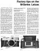
The Leica M2 illustrated in Fig. 1 is
a slightly simplified version of the
original M-series Leica, the M3. The
M3 set the design precedents for the
other M-series Leicas: the Ml
(further simplified from the M2) and
the MP (a special model for press
photographers quite similar to the
M2). More recently, the M4 (an
improved version of the M3) took over
the top roost. But all the Leica models
mentioned are nearly identical from
the technician's viewpoint. Only the
M5, which we'll not discuss here,
represents a radical departure from
the original design.
If you've been in the repair business
for any length of time, you can no
doubt take a Leica apart. But we find
that most technicians spend time
removing parts that could just as well
be left in place. So we'll outline the
disassembly techniques to reach the
adjustments and timing points of
concern.
Starting with the top cover plate
disassembly, remove the screw at the
top of the lens mounting ring, Fig. 1.
This screw is normally sealed with a
black locking agent. Since the screw
must be removed to pull either the top
cover plate or the body shell, you can
frequently tell from the condition of
the locking agent whether or not the
camera has previously been
disassembled.
Next, remove the camera's base
plate as you would for loading film.
The Leicas based on the M3 design
carry over the load-from-the-bottom
technique of the screw-mount Leicas.
But the M-series Leicas added a
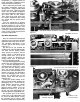
hinged back to facilitate loading. You
can remove the hinged back by
pushing the release pin from left to
right in Fig. 2.
Reaching into the supply-spool
cavity, wedge the rewind fork to
prevent it from turning. Then, use a
Multispan wrench to unscrew the
cover screw that holds the rewind
knob, Fig. 3. An exception here is the
M4—the rewind knob in the M4 sits at
a convenient cant and is held by a
setscrew.
Probably one of the main
disassembly problems faced by the
technician is the removal of the wind
lever cover screw, Fig. 3. The wind
lever cover screw has a right-hand
thread, but it may be extremely tight.
To avoid scarring the polished
RANGEFINDER WINDOW
FRAME LINE
MASK WINDOW
COVER SCREW FOR
VERTICAL RANGEFINDER
ADJUSTMENT
Figure 1
Figure 2
VIEWFINDER WINDOW
RELEASE PIN
FRAME LINE SELECTOR LEVER
REWIND LEVER