
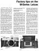
Factory Tips


surface, use a Flexiclamp wrench or a
split collet to unscrew the wind lever
cover screw. You can then lift off the
wind lever and, in the M2, the counter
dial.
Also, if you're working on the M2,
remove the cover plate retaining
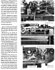
screw shown in Fig. 3. You won't find
this retaining screw in the M3 or the
M4 — instead, unscrew the retaining
ring accessible after removing the
wind lever. The reason for the
difference is that the AA2 has an
external, manually set counter dial.
But in the M3 and AA4, the counter dial
is underneath the top cover plate. The
spring-loaded counter dial in the M3
and AA4 automatically returns when
you pull out the film take-up spool.
Another tricky part to remove is the
retaining ring around the rewind
shaft. The problem here is that
standard tools can't do the job — there
isn't enough room for a Flexiclamp
wrench and there are no notches for a
Multispan wrench. So here's one place
that you may wish to design a special,
tubular tool that fits over the retaining
ring.
The remaining top cover plate
components are no problem. Take out
the speed knob retaining screw, Fig.
3, and lift off the speed knob. And
remove the four screws holding the
accessory shoe, also shown in Fig. 3.
Lift off the accessory shoe, the
accessory shoe pressure plate, and
the spring.
Proceeding to the back of the
camera, unscrew the two flash socket
cover rings and the two flash socket
bushings. If you're working on the M3,
also unscrew the eyepiece frame.
Now, lift off the top cover plate.
Before we go into the adjustments
and timing points now visible, we'll
complete the disassembly of the body
shell and the rangefinder, Fig. 4. You
may, however, wish to replace the
wind lever with its cover screw to
examine the operation at the top of the
camera. Then, turn over the camera
and remove the three screws holding
the bottom cover plate, Fig. 5. Lift off
the bottom cover plate and the base
lock plate.
Adjustments At The Bottom Of
The M-Series Leica
Several adjustment points are now
visible at the bottom of the camera,
Fig. 6. Notice that the M-series Leicas
departed from the conventional
methods of locking the curtain take-up
rollers. To adjust the curtain tensions,
REWIND
KNOB
COVER
SCREW
COUNTER DIAL
WIND LEVER
COVER SCREW
COVER
PLATE
RETAINING
SCREW
SPEED KNOB
RETAINING SCREW
ACCESSORY SHOE SCREWS
Figure 3
RANGEFINDER
ASSEMBLY
SPEED SELECTOR
WIND CAM
SAFETY SWITCH FOR "FP" SYNC CONTACTS
Figure 4
BOTTOM COVER PLATE RETAINING SCREWS
Figure 5
PIVOT PLATE
FOR CURTAIN
WIND GEAR
AND OPENING
CURTAIN LATCH
BASE LOCK PLATE
CLOSING CURTAIN
TAKE-UP ROLLER
END OF OPENING
CURTAIN LATCH
"X"-SYNC ADJUSTMENT
DRUM BEARING PLATE
LOCKING
COLLARS
OPENING CURTAIN
TAKE-UP ROLLER
CLOSING CURTAIN
BRAKE ADJUSTMENT
SETSCREW
ADJUSTMENT
FLAT
RELEASE
SPRING
Figure 6