
Installation Manual


ProVision 3 Installation Manual
8100-35521-00
Rev. A0
Leidos Security Detection & Automation, Inc. – Proprietary Page 111 of 119
© 2020 Leidos. All rights reserved
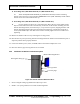
15. If installing OCP (1000-24266-00 ROW) or (1000-24641-00 TSA)
16. Attach OCP (1000-24266-00 ROW) or (1000-24641-00 TSA) to monitor mounting
bracket removed in step 1 using four M4-.7X8MM PPH screws (0201-10001-08). Install with the
bracket release lever toward the monitor top.
17. If installing OCP (1000-30159-00 ROW) or (1000-27624-00 TSA)
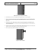
18. Lay the monitor face down on a protected surface. Place the four spacers (0235-27550-
00) over each of the holes in the recessed cavity on the back of the monitor. Carefully place the
monitor mounting bracket, removed in step 1, on top of the four spacers, aligning the holes. The
monitor mounting bracket locking lever should be towards the top of the monitor. Drop the 4
screws (0201-10001-14) in each hole of the bracket. Carefully tighten each screw without over
tightening.
19. Remove the monitor cable cover by removing the securing screws.
20. Place monitor on pole by lowering monitor mounting bracket into monitor mount attached to pole. It
snaps into position when properly installed.
21. Connect the monitor power, video, and USB cables to the monitor. Replace the cover.
22. Place the cables in gray sleeving and wire-tie as needed.
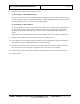
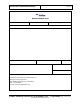
42.2 Installation of Monitor Fixed Mount Option
Figure 125: Monitor Attached With Fixed Riser
1. Insert rectangular tubing cap (0295-23713-00) in top of riser.
2. Install 1-3/8” nylon grommet in riser cable round through-hole.
Monitor Mounting Bracket
Nylon grommet
Two hole plugs
Rectangular tubing cap