
Installation Manual


ProVision 3 Installation Manual
8100-35521-00
Rev. A0
Leidos Security Detection & Automation, Inc. – Proprietary Page 112 of 119
© 2020 Leidos. All rights reserved
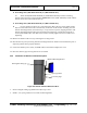
23.
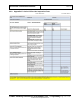
Figure 126: Screws and Spacers Installed
3. Feed monitor power, video, and USB cables through mid-panel. Secure the panel.
4. Slip four .88”spacers (3000-22752-14) onto four M8x30mm FSHC screws, (0201-22862-30) and
thread loosely into OCP mounting bracket (3000-23601-00X) where monitor is to be located. See
Figure 126.
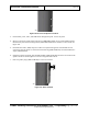
5. Extend monitor video, USB, and power cables from system through riser from behind for later
connections. Ensure cables are enclosed in black sleeving (0580-10038-16) secured with black tie-
wraps, 0380-10030-00.
6. Using the keyholes and slots, slide OCP Fixed Riser (3000-23700-00) onto the screws between the
spacers and screw heads. Tighten four screws using 6mm Allen driver.
7. Press two plastic plugs (2000-27380-00) in screw access holes.
24.
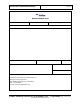
Figure 127: Riser Installed