
Installation Manual


ProVision 3 Installation Manual
8100-35521-00
Rev. A0
Leidos Security Detection & Automation, Inc. – Proprietary Page 113 of 119
© 2020 Leidos. All rights reserved
8. Place monitor face-down on flat protected surface.
25. If installing a OTEK Monitor (older)
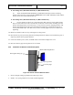
26. Place the OCP monitor mount assembly (1000-27378-00) over the four holes on the back of the
monitor and loosely install two M4 x 8mm PPH screws (0201-10001-08) in top two mounting holes.
Carefully tighten the four screws without over tightening them.
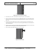
27. If installing a GVision Monitor
28. Lay the monitor face down on a protected surface. Place the four spacers (0235-27550-00) over
each of the holes in the recessed cavity on the back of the monitor. Carefully place the monitor
mounting bracket (1000-27378-00), on top of the four spacers, aligning the holes. Drop the four
screws
(0201-10001-14) in each hole of the bracket. Carefully tighten each screw without over tightening.
9. Remove monitor cable cover by removing securing screws. Retain screws.
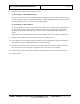
10. Secure monitor mount assembly (1000-27378-00) to riser with slotted holes upward (manufacturer
logo readable) using two M8x16mm PFH screws (0201-20413-16).
11. Place monitor on monitor mount with the two loosely install screws in slots to support. Install two
more screws in lower mounting holes. Tighten all four screws. Do not over-tighten.
12. Connect monitor power, video, and USB cables to monitor. Replace cover using retained screws.
13. Dress the cables.