
Installation Manual


ProVision 3 Installation Manual
8100-35521-00
Rev. A0
Leidos Security Detection & Automation, Inc. – Proprietary Page 114 of 119
© 2020 Leidos. All rights reserved
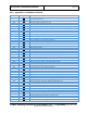
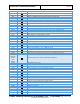
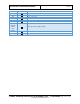
43.0 Appendix D: Installation Checklist
Section
Completed
Task
4.0
Ensure there is enough space to unpack crates and install scanner, and there is clear
access to the install site
4.2
Open and unpack scanner crate
4.3
Open and unpack installation kit crate
5.0
Assemble Genie Lifts
5.0
Inspect Genie Lifts prior to use (Ref: Appendix E)
7.0
Attach ramps to scanner crate
7.0
Attach caster end plates to upper/lower frame assembly
7.0
Attach casters to caster end plates
7.0
Insert leverage bars and lift assembly onto casters
7.0
Roll assembly down ramps and off scanner crate
8.0
Move assembly to install location
8.0
Orient assembly so it faces desired direction
8.0
Pivot casters and lower assembly to floor
8.0
Remove casters and caster end plates
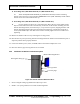
9.1
Remove outer shipping leg bolts
9.1
Install lifting brackets
9.1
Insert lifting bars
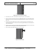
9.1
Install columns and column head clamps
9.1
Position Genie Lifts
9.1
Connect cradle forks to lifting bars with quick-release pins
9.1
Chock wheels of Genie Lifts
9.1
Remove remaining shipping leg bolts
9.2
Turn Genie Lift cranks to raise assembly past midway
9.2
Install stop bolts at midway point (bolt heads inward)
9.2
Raise assembly to top, 2" past bolt holes
9.2
Move stop bolts from midway point to upper position
9.2
Turn Genie Lift cranks to lower assembly 2"
9.2
Install upper column bolts (bolt heads outward)
9.2
Install lower column bolts (bolt heads inward)
9.2
Torque 3 of 4 column base bolts, then column head clamp screws
9.2
Torque upper and lower column bolts, then safety stop bolts
9.2
Loosen shipping leg top bolts
9.2
Install two cross braces between shipping legs
9.2
Remove L bracket bolts, then shipping leg top bolts
9.3
Lower and remove Genie Lifts, brackets and shipping legs
10.1
Verify leveling feet are fully raised
10.2
Set bolt-on side frames in place (remove feet if necessary)
10.2
Secure bolt-on side frames (reattach feet if removed)
10.3
Install Isolation Pads [OPTIONAL] if required.
10.4
Lower feet to raise scanner off floor
10.5
Install seismic brackets [optional] – refer to 8000-22056-IP
10.6
Level scanner, ensure all feet are touching floor, and lock feet in place
2.2
Use the lockout/tagout procedure to prevent injury
11.1
Torque upper frame bolts
0
Install bottom outer radome angle brackets