
Installation Manual

ProVision 3 Installation Manual
8100-35521-00
Rev. A1
Leidos Security Detection & Automation, Inc. – Proprietary Page 19 of 119
© 2020 Leidos. All rights reserved
4.0 Crate Unpacking
4.1 General Guidelines
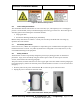
The area should be large enough to unpack and set aside the contents of the two crates until needed. The
installation kit arrives in one crate, and the scanner is in the second, larger crate:
Installation Kit Crate
Hardware kit, genie lifts, brackets, casters, ramps, calibration aids required to move and install the
ProVision 3 scanner (including additional brackets and hardware necessary to install other Leidos
products but not needed for the ProVision 3).
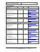
Scanner Crate
Upper/lower frame assembly with shipping legs (4) and power input box/cables attached
Columns (2 left and 2 right)
Column head clamps (4)
Bolt-on side frames (2)
Outer windows (1 plain and 1 with stance or two plain)
Outer windows angle brackets (2 top and 2 bottom)
Outer windows bracket supports (4)
Outer windows bracket retainers (4)
Inner radomes (2)
Inner radome top angle rails (2)
Inner radome base flange support brackets (2)
Inner radome edge support brackets (4)
Antenna masts (2)
Cosmetic mast wrap (2)
Entrance/exit covers (2 left and 2 right)
Middle OCP cover
Plain middle cover
Middle belt barrier covers (2)
Upper/lower cover with switch/power input w/ cover plate
Plain upper/lower covers (3)
Ceiling panel
Roof
Top side covers (2)
Top entrance/exit covers (2)
Middle cover brace brackets (12)
Housing brace brackets (2)
Floor cover trim pieces (2)
Floor side panels (2) and center panel
Entrance/exit ramp assemblies (2)