
Installation Manual

ProVision 3 Installation Manual
8100-35521-00
Rev. A1
Leidos Security Detection & Automation, Inc. – Proprietary Page 41 of 119
© 2020 Leidos. All rights reserved
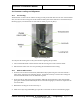
9.2 Upper Frame Assembly Lifting
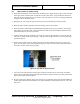
1. Rotate the crank handles on the Genie Lifts simultaneously to begin lifting the upper frame assembly.
If the upper frame assembly does not separate from the lower frame, verify that all bolts have been
removed securing shipping legs to lower frame, and verify there are no wires or cabling hooked from
the upper frame to the lower frame.
2. During the lift, ensure that the upper frame stays level by simultaneously raising both lifts.
3. Raise the upper assembly past the holes at the midway point of the columns.
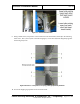
4. Insert four M12 x 130mm SHC bolts (020220433-30) pointing away from each other, such that the
bolt heads are toward the inside. Thread an M12 flat washer (0221-10076-00) and an M12 hex nut
(0216-20441-00) over the end of each bolt.
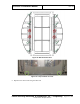
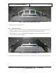
5. Continue raising the upper assembly to the top of the columns, approximately 2 in. [5.1cm] past the
bolt holes, as shown in the following figure. This provides enough clearance to insert the stop bolts
past the lifting bars.
6. Remove the stop bolts from the midway point of the columns and move them one at a time to the
upper stop bolt holes, again with the bolts pointing away from each other and the bolt heads toward
the inside, as shown in the following figure.
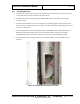
Figure 36: Stop Bolt in Upper Bolt Hole
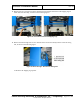
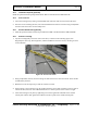
7. Lower the Genie Lifts until the column upper and lower bolt holes line up, then insert four M16 x
40mm column upper bolts (0202-20431-40) and four M16 x 40mm column lower bolts (0202-20431-
40) as shown in the following figures.
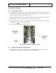
8. Be sure to follow the direction of the bolts as shown in the following figure right, thread an M16 flat
washer (0221-10051-00) and an M16 hex nut (0216-20432-00) over the end of each bolt. Leave the
bolts loose.