
Installation Manual

ProVision 3 Installation Manual
8100-35521-00
Rev. A1
Leidos Security Detection & Automation, Inc. – Proprietary Page 45 of 119
© 2020 Leidos. All rights reserved
10.0 Scanner Leveling and Alignment
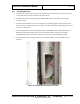
10.1 Pre-leveling
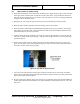
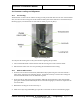
The ProVision 3 scanner arrives with the leveling feet fully raised and with two lock nuts on the threaded
stem, one between the leveling foot and the welded column plate and the other above the welded nut (see
following figure; note that the bolt-on side frame is already in place in photo).
Figure 41: Leveling Foot
To verify that the leveling feet are fully raised before beginning this procedure:
1. Turn each threaded stem counterclockwise until the leveling foot can be raised no further.
2. Ensure that the lower lock nut is not preventing the threaded stem from turning.
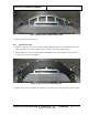
10.2 Bolt-On Side Frames
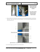
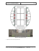
1. Set the first of two bolt-on side frames (3810-10073-00) in place along one side of the scanner’s
lower frame, as shown in the following figures. It might be necessary to remove the leveling feet
from their threaded stems to set the side frame in place.
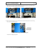
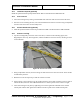
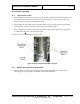
2. Secure the bolt-on side frame using four M10 x 45mm HC bolts (0201-20777-45) and four M10
spring lock washers (0221-10003-00) as shown in the following figure, no bolts are required for the
two center holes.
3. Reattach the leveling feet if removed in step 1.
4. Install one U-style clip (410-23861) per open hole on the frame as shown in the following figure.