
Installation Manual

ProVision 3 Installation Manual
8100-35521-00
Rev. A1
Leidos Security Detection & Automation, Inc. – Proprietary Page 47 of 119
© 2020 Leidos. All rights reserved
10.3 Isolation Footpads (optional)
Install the optional isolation pads per 8100-23121-TM or Leidos document: 8000-22070-IP
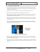
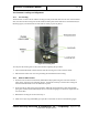
10.4 Feet Lowered
1. Lower the leveling feet by turning each threaded stem clockwise until each foot touches the floor.
2. Once the feet are touching the floor, turn each threaded stem clockwise a full turn using an adjustable
wrench to raise the scanner off the facility floor.
10.5 Seismic Bracket Kit (optional)
3. Install the optional seismic bracket kit per 8100-23121-TM or Leidos document: 8000-22056-IP.
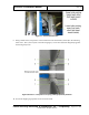
10.6 Scanner Leveling
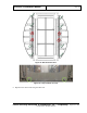
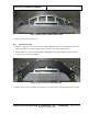
1. Lay the level diagonally across the center of the floor, as shown in the following figure, then
diagonally the other way, then lengthwise, and then widthwise across the scanner, checking for level
in each direction.
Figure 44: Cross-Level Check
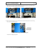
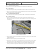
2. Using an adjustable wrench, turn the leveling feet bolts clockwise to raise the scanner where needed
as indicated by the level.
3. Recheck for level and repeat step 2 until the scanner is leveled.
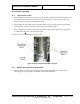
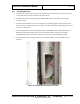
4. After leveling, if any leveling foot is not touching the floor, turn its bolt clockwise to lower it until it
touches the floor, then turn it an additional half turn so it bears a portion of the scanner’s weight.
5. Lock each leveling foot in place by tightening one lock nut against the underside of the welded
column plate and the other against the welded nut on the top side of the welded column plate.