
Installation Manual

ProVision 3 Installation Manual
8100-35521-00
Rev. A1
Leidos Security Detection & Automation, Inc. – Proprietary Page 48 of 119
© 2020 Leidos. All rights reserved
11.0 Scanner Assembly
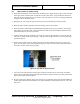
11.1 Upper Frame Torque
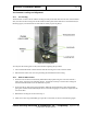
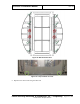
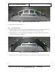
1. Using a 6mm hex bit socket and 3/8
th
” drive torque wrench, torque the 16-column head clamp screws
to 13.6 Nm (10.0 ft-lb) using a cross pattern to prevent binding the screws (see Figure 45). The
spacing on both sides of each clamp should be equal.
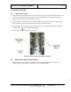
2. Using a 24mm wrench, 24mm socket, and half inch drive torque wrench, torque the eight column
upper and lower bolts to 67.8 Nm (50.0 ft-lb) (refer to the following figure).
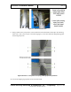
3. Using a 10mm hex key, 19mm socket, and 3/8
th
” drive torque wrench, torque the four stop bolts to
27.1 Nm (20.0 ft-lb) (refer to the following figure).
4. Verify system remained aligned per section 10.6.
Figure 45: Other Column Screws/Bolts Torqued
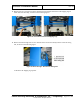
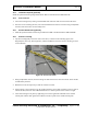
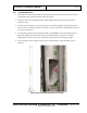
11.2 Bottom Outer Window Angle Brackets
1. Install the first of two bottom outer radome angle brackets (3810-10065-00), as shown in the
following figure, using four M6 x 12mm FHC screws (0201-10069-12).