
Installation Manual


ProVision 3 Installation Manual
8100-35521-00
Rev. A1
Leidos Security Detection & Automation, Inc. – Proprietary Page 51 of 119
© 2020 Leidos. All rights reserved
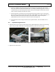
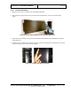
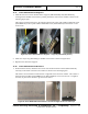
6. Install two additional mounting brackets onto the columns at the opposite end of the scanner;
these were used for the barrier belt installed later. As with the first mounting bracket, use the set
of holes directly over the leveling foot (as shown in the previous figure left and center), not the
other set that is around by the end of the scanner.
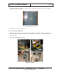
7. Install each bracket so that the face of each bracket points away from the center of the scanner.
Each mounting bracket is fastened using three M6 x 16mm FBHS screws (0201-10291-16), two
M6 fender washers (0221-10027-00) on the top and bottom holes, and one curved plate
(3000-23601-01) on the center hole as shown circled in red in Figure 49.
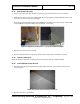
8. Leave the bracket loose enough so that it can be repositioned later, when the middle cover is
installed.
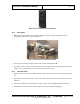
11.5 Top Window Angle Brackets
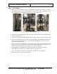
1. Install the first of two top outer window angle brackets (3810-10076-00) as shown in the following
figure, using five M8 x 20mm FHC screws (0201-20452-20). Ensure the bolts are tight.
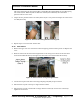
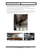
Figure 49: Top Outer Radome Angle Bracket with Bolt Inserted (Right)
2. Repeat for the other bracket.