
Installation Manual


ProVision 3 Installation Manual
8100-35521-00
Rev. A1
Leidos Security Detection & Automation, Inc. – Proprietary Page 53 of 119
© 2020 Leidos. All rights reserved
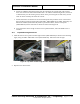
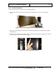
Figure 52: Power Switch in the On Position
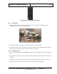
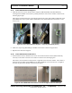
11.8 Swing Arm
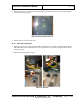
1. Move swing arm by hand to the calibration position (across the scanner, 90 degrees from the
longitudinal center line), as shown in Figure 53.
Figure 53: Swing Arm in Calibration Position
2. Turn the power off by pressing the portion of the power switch labeled “O”.
3. Unplug the scanner’s power cord from the electrical outlet and use the lockout/tagout procedure (see
Section 2.2) to prevent injury due to accidental re-start of the scanner.
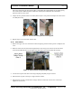
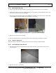
11.9 Antenna Masts
1. Retrieve the two antenna masts (1000-11899-00), The masts are packed in two-inch long corrugated
box.
2. Open the box and remove the mast. It does not matter which side the mast is mounted on as they are
identical.
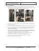
3. Position the mast close to the swing arm and gently rotate the mast upright with the L bracket up.
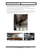
4. Attach the L bracket of the mast to the swing arm as shown in the following figures.