
Installation Manual


ProVision 3 Installation Manual
8100-35521-00
Rev. A1
Leidos Security Detection & Automation, Inc. – Proprietary Page 54 of 119
© 2020 Leidos. All rights reserved
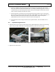
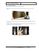
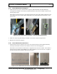
The mast is fastened to the arm with five M12 x 35mm HC bolts (0201-10005-35), five M12 spring
lock washers (0221-10002-00) and five M12 flat washers (0221-10076-00). Four around the
perimeter and one in the center.
5. Torque the four perimeter bolts to 54.2 Nm (40.0 ft-lb) in a cross pattern and torque the center bolt to
37.9 Nm (28.0 ft-lb).
Figure 54: Antenna Mast Being Attached to Swing Arm
6. Repeat steps 2 to 5 for the other antenna mast.
11.10 Mast Cables
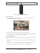
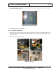
1. Remove the upper rear cover from the first mast and gently pull the coiled-up wires out. Replace the
cover.
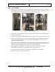
2. Route the wires from the first mast through the hole in the swing arm to the left of the mast when
viewed from behind the mast (to the right of the mast when viewed from inside the scanner).
Figure 55: Cables Routed Through Swing Arm Hole
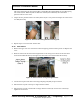
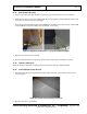
3. Connect the 25-pin D-sub cable to the image sampling unit (ISU) 25-pin connector.
4. Ensure that the 13 pins in the top row align with the 13 holes.
5. Ensure that the 12 pins in the bottom row align with the 12 holes (do not force the connection).
Tighten the screw locks.