
Installation Manual


ProVision 3 Installation Manual
8100-35521-00
Rev. A1
Leidos Security Detection & Automation, Inc. – Proprietary Page 58 of 119
© 2020 Leidos. All rights reserved
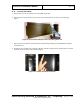
11.13 Entrance/Exit End Cap
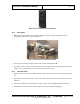
1. Remove the column bolt (bolt #4) that was left loose in each column when they were installed.
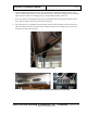
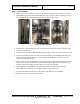
2. Install one left entrance/exit cover (3000-22286-01) and one right one (3000-22286-00) at one end of
the scanner as shown in the following figures.
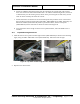
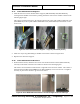
Each cover is fastened with two M6 x 16mm FBHS screws (0201-22775-16) in the top and three M8
x 10mm FBHS screws (0201-10292-10) in the bottom. Leave loose.
Figure 62: Right Entrance/Exit Cover – Top (Left) and Bottom (Right)
3. Repeat for the other end of the scanner.
4. Put the column bolts back in and, using a 24mm socket, torque them to 94.9 Nm (70.0 ft-lb).
11.14 Vibration Control Kit
Install the vibration control kit as explained in Section 14 of this manual or 8100-21350-IP.
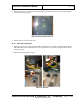
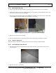
11.15 Outer Window Scratch Guards
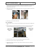
1. Peel and remove the scratch guard film from both sides of the first outer window as shown in the
following figure.
Figure 63: Scratch Guard Film Being Removed
2. Repeat for the other outer window.