
Installation Manual


ProVision 3 Installation Manual
8100-35521-00
Rev. A1
Leidos Security Detection & Automation, Inc. – Proprietary Page 72 of 119
© 2020 Leidos. All rights reserved
11.32 Plain Middle Cover
1. Locate the plain middle cover (3000-27081-00). It can fit on either the right or left side of the
electrical enclosure end.
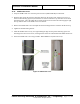
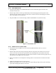
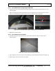
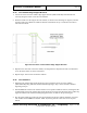
2. Slide the edge with the notch at top and bottom (see the following figure) into the pocket of the
entrance/exit cover and line up the screw hole shown circled in red in the following figure with the
hole on the middle cover brace bracket.
3. The plain middle cover is fastened using one M6 x 16mm FBHS screw (0201-22775-16).
Figure 77: Plain Middle Cover
11.33 Middle Covers for Barrier Belt
1. Locate the first of two middle covers for barrier belt (3000-27079-00). The two covers are
interchangeable.
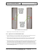
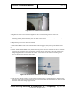
2. Slide the edge nearest the four large mounting holes into the pocket of the entrance/exit cover and
check to see if the four holes line up with those on the mounting bracket for the barrier belt at the
motor/pulley end. Also check that the screw hole shown circled in red in the following figure lines up
with the hole on the middle cover brace bracket.
3. Remove the middle cover and adjust the mounting bracket for the barrier belt if needed so all holes
line up.
4. Tighten the mounting bracket for the barrier belt.
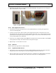
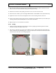
5. Install the first middle cover for barrier belt by once again sliding its edge into the pocket and lining
up the four mounting holes and one screw hole.