
Installation Manual

ProVision 3 Installation Manual
8100-35521-00
Rev. A1
Leidos Security Detection & Automation, Inc. – Proprietary Page 73 of 119
© 2020 Leidos. All rights reserved
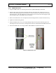
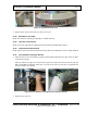
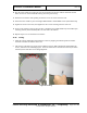
6. Fasten the middle cover for barrier belt using one M6 x 16mm FBHS screw (0201-22775-16).
4.
Figure 78: Middle Covers for Barrier Belt
7. Repeat steps 1 to 6 for the other middle cover for barrier belt.
11.34 Upper/Lower Cover with Switch/Power Input
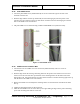
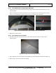
1. Orient the upper/lower cover with switch/power input so that the cutout is located where the power
input box is located (lower electrical enclosure end or upper motor/pulley end).
2. Slide one side (vertical edge) into the pocket of the entrance/exit cover, as you did for the middle
covers previously, then slide the other side into the pocket of the opposite entrance/exit cover.
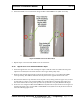
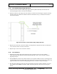
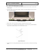
3. Ensure that the holes line up with those on the top side cover (if being used as an upper cover) or bolt-
on side frame (if a lower cover) and the middle cover underneath (see following figure right), and
also ensure that the holes on the power input box line up with the cover plate (discussed in step 4).
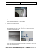
4. Secure the cover using three M6 x 16mm FBHS screws (0201-22775-16) as shown circled in green in
the following figure center, and two M6 x 25mm FBHS screws (0201-22775-25) as shown circled in
red in the following figure center.