
Installation Manual

ProVision 3 Installation Manual
8100-35521-00
Rev. A1
Leidos Security Detection & Automation, Inc. – Proprietary Page 74 of 119
© 2020 Leidos. All rights reserved
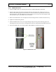
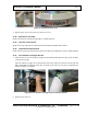
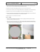
5. Attach the cover plate with 3" rectangular hole (3000-23668-00) to the upper/lower cover using four
M4 x 16mm BHS screws (410-22394).
Figure 79: Upper/Lower Cover with Switch/Power Input in Lower Position
11.35 Plain Upper/Lower Covers
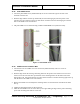
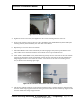
1. Locate the first of three plain upper/lower covers (3000-27082-00). The three plain upper/lower
covers are interchangeable.
2. As in the previous section, slide one side (vertical edge) into the pocket of the entrance/exit cover,
then slide the other side into the pocket of the opposite entrance/exit cover. Ensure that the holes line
up with those on the top side cover (if being used as an upper cover) or bolt-on side frame (if a lower
cover) and the middle cover underneath.
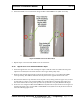
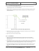
3. Secure the cover using three M6 x 16mm FBHS screws (0201-22775-16) and two M6 x 25mm FBHS
screws (0201-22775-25) in the locations shown in the previous figure.
4. Repeat steps 1–3 for the other two covers.
11.36 Label Kit
Install a label kit per Appendix E or 8600-23942-IP.
11.37 Top Entrance/Exit Covers
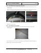
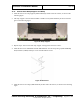
1. Locate the first of two top entrance/exit covers (3000-27084-00) and install it by lining up the holes
along the top, shown circled in green in the following figure, with those on the roof.
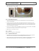
2. The top entrance/exit cover is fastened using three #8 x .750 PTH screws [0200-20643-12] and three
#8 flat washers (0220-20783-00). Leave screws loose until final cover fitting/alignment.