
Installation Manual

ProVision 3 Installation Manual
8100-35521-00
Rev. A1
Leidos Security Detection & Automation, Inc. – Proprietary Page 75 of 119
© 2020 Leidos. All rights reserved
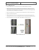
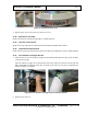
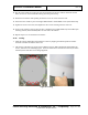
Figure 80: Top Entrance/Exit Cover
3. Repeat steps 1 and 2 for the other top entrance/exit cover.
11.38 Belt Barrier Assembly
Install the belt barrier assembly per Appendix F or 8000-21314-IP.
11.39 Operator Control Panel
Install the OCP per Appendix F or 8000-21314-IP System Mounted Resolution Station.
11.40 Optional Resolution Station
Install optional system mounted Resolution station per 8100-23121-TM option section or 8600-26545-IP
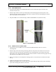
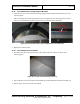
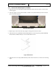
11.41 Inner Radome Top Angle Bracket
1. Install the first of two inner radome top angle brackets (3810-10075-00) to the upper frame as shown
in the following figure.
The inner radome top angle rail is fastened to the upper frame (above the entrance and exit) with four
M8 x 16mm PFH screws([0201-20413-16). Leave the screws loose for now; they are tightened after
the inner radomes are installed.
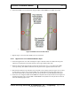
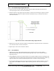
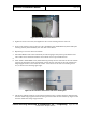
Figure 81: Inner Radome Top Angle Rail and Attachment Point
2. Repeat for the other rail.