
Installation Manual

ProVision 3 Installation Manual
8100-35521-00
Rev. A1
Leidos Security Detection & Automation, Inc. – Proprietary Page 76 of 119
© 2020 Leidos. All rights reserved
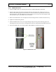
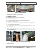
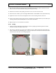
11.42 Inner Radome Base Flange Support Brackets
1. Install the first of two inner radome base flange support brackets (3810-10103-00) as shown in the
following figure.
The inner radome base flange support bracket does not require screws or other fasteners. It has two
holes to accommodate the two guide pins that stick up from the bolt-on side frames.
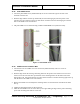
Figure 82: Inner Radome Base Flange Support Bracket and Guide Pin
2. Repeat for the other bracket.
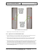
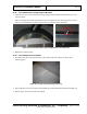
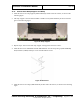
11.43 Inner Radome Scratch Guards
1. Peel and remove the scratch guard film from both sides of the inner radome, as shown in the
following figure.
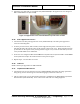
Figure 83: Scratch Guard Film Being Removed
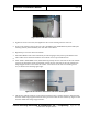
2. Wipe both sides of the inner radome with the ESD wipes (490-26003) included in the hardware kit.
3. Repeat steps 1 and 2 for the other inner radome.