
Installation Manual

ProVision 3 Installation Manual
8100-35521-00
Rev. A1
Leidos Security Detection & Automation, Inc. – Proprietary Page 77 of 119
© 2020 Leidos. All rights reserved
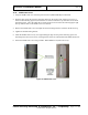
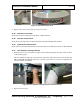
11.44 Inner Radome Edge Support Brackets
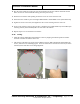
1. Locate two of the four inner radome edge support brackets (3000-22310-00) and install the first
vertically along the side of one of the inner radomes.
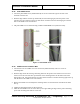
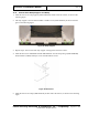
2. Slide the bracket over the edge of the inner radome, as shown in the following two figures, such that
the edge of the inner radome fits inside the bracket and the holes line up. The bracket uses tabs to
lock onto the radome.
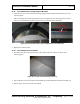
Figure 84: Placement of Inner Radome Edge Support Brackets
3. Repeat for the other side of the inner radome, ensuring that the L-shaped ends of the second bracket
are on the same surface as for the first bracket.
4. Repeat steps 1 and 2 for the second inner radome.
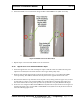
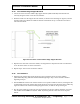
11.45 Inner Radomes
1. With the inner radome edge support brackets in place, install the first of two inner radomes
(3810-10061-00) using either the standard method beginning in Step 2 or the alternative method
beginning in Step 6.
2. Standard Method: Lift the inner radome and move it into position inside the scanner, ensuring that the
L-shaped ends of the inner radome edge support brackets are facing and contacts the inner radome top
angle rail and the inner radome base flange support bracket, as shown in the previous figure.
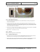
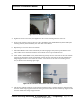
3. Flex the inner radome by pressing in at the top and bottom of the inner radome and fasten it in place
with 10 M6 x 16mm FBHS screw (0201-10291-16) starting with the center holes on the top and
bottom.