
Installation Manual

ProVision 3 Installation Manual
8100-35521-00
Rev. A1
Leidos Security Detection & Automation, Inc. – Proprietary Page 78 of 119
© 2020 Leidos. All rights reserved
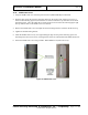
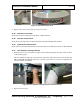
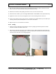
Figure 85: Inner Radome Fastened in Place
4. Tighten the center screws first, then tighten the outer screws working from the center out.
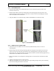
5. Secure inner radome to end cap using six #8 x .625 PTH screws [0200-20643-10] and six M4 nylon
retaining washers [0221-29376-00] 3 on each side of the radome.
6. Repeat Steps 2–5 for the other inner radome.
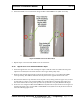
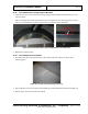
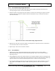
7. Alternative Method: The center slotted hole (see following figure left) at the top and bottom of the
inner radome can be utilized to hook the inner radome onto two pre-installed screws.
5.
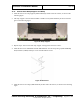
8. Insert an M6 x 16mm FBHS screw (0201-10291-16) partway into the center hole of the inner radome
top angle rail (inside the scanner) and another partway into the center hole of the inner radome base
flange support bracket on one side of the scanner. Leave about 2/3 of each screw sticking out for
now, as shown in the following figure right.
Figure 86: Inner Radome Slotted Hole and Screw Sticking Out
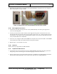
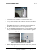
9. Lift the inner radome and move it into position inside the scanner, ensuring that the L-shaped ends of
the inner radome edge support brackets are facing and will contact the inner radome top angle rail and
the inner radome base flange support bracket.