
Installation Manual

ProVision 3 Installation Manual
8100-35521-00
Rev. A1
Leidos Security Detection & Automation, Inc. – Proprietary Page 79 of 119
© 2020 Leidos. All rights reserved
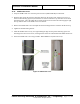
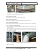
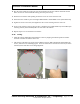
10. Flex the inner radome by pressing in at the top and bottom of the inner radome and fit the slotted
holes over the two screw heads left sticking out in the previous step.
11. Slide the inner radome while pushing in until the screws are at the end of the slots.
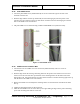
12. Fasten the inner radome in place with eight additional M6 x 12mm FBHS screws (0201-10291-16),
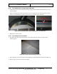
13. Tighten the center screws first, then tighten the outer screws working from the center out.
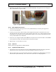
14. Secure inner radome to end cap using six #8 x, 750 PTH screws (0200-20643-12) and six M4 nylon
retaining washers (0221-29376-00) three on each side of the radome.
15. Repeat steps 6 to 13 for the other inner radome.
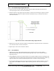
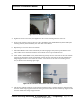
11.46 Ceiling
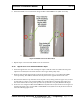
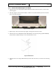
1. Install the ceiling (1000-20731-00) inside the scanner by aligning the indented portions with the
electrical enclosure end and the motor end.
2. The ceiling is fastened to the upper frame weldment using ten M6 x 20mm SHC (0201-20419-20)
screws, as shown in the following figures. Leave the screws above the entrance and exit (circled in
red below) loose until final cover fitting/alignment.
Figure 87: Ceiling