
Datasheet


3
19
Max.
0.5
20
Max.
3-P=2.54
1
2
3
4
+V
OUT
6 5
8.8 5.4
1.3
5
-V or 0
0
3.5
3
HX 50-P
3 8.8 5.4
1.2
3
19
Max.
0.5
20
Max.
3-P=2.54
1
2
3
4
+V
OUT
5
-V or 0
0
3.5
3
10.85
3.5
d
10.85
6
6
15.4 Max.
15.4 Max.
Top view
Lot No.
HX 05-P
41123
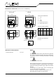
HX 03...25-P
Dimensions HX 03..50-P (in mm. 1 mm = 0.0394 inch)
Terminal Pin Identification
1 ..... -15 V
2 ..... 0 V
3 ..... +15 V
4 ..... Output
5 ..... Primary input Current (+)
6 ..... Primary input Current (-)
Primary conductor diameter
Safety
This transducer must be used in electric/electronic equipment
with respect to applicable standards and safety requirements
in accordance with the following manufacturer's operating
instructions.
Caution, risk of electrical shock
When operating the transducer, certain parts of the module can
carry hazardous voltage (eg. primary busbar, power supply).
Ignoring this warning can lead to injury and/or cause serious
damage.
This transducer is a built-in device, whose conducting parts
must be inaccessible after installation.
A protective housing or additional shield could be used.
Main supply must be able to be disconnected.
070313/11 www.lem.com
LEM reserves the right to carry out modifications on its transducers, in order to improve them, without prior notice.
Page 2/2
HX 03-P 05-P 10-P 15-P
d 0.6 0.8 1.1 1.4
HX 20-P 25-P 50-P
d 1.6 1.6 12 x 6.3
Secondary pins dimension
0.5 x 0.25
HX 03..25-P
HX 50-P
Mechanical characteristics
• General tolerance ± 0.5 mm