AX45Q Intel® Q45 LGA775 socket for Intel® Core™2 Quad ATX Motherboard User’s Manual Ver. 1.
AX45Q Contents Safety information ............................................................................................................. 4 About this guide ................................................................................................................ 5 Typography ........................................................................................................................ 6 AX45Q specifications summary ......................................................................
User’s Manual 2.1 Managing and updating your BIOS .......................................................................... 43 2.1.1 Creating a bootable floppy disk ........................................................................... 43 2.2 BIOS setup program .................................................................................................. 44 2.2.1 Legend Box ......................................................................................................... 44 2.2.2 List Box .
AX45Q Safety information Electrical safety y To prevent electrical shock hazard, disconnect the power cable from the electrical outlet before relocating the system. y When adding or removing devices to or from the system, ensure that the power cables for the devices are unplugged before the signal cables are connected. If possible, disconnect all power cables from the existing system before you add a device.
User’s Manual About this guide This user guide contains the information you need when installing and configuring the motherboard. How this guide is organized This manual contains the following parts: y Chapter 1: Product introduction This chapter describes the features of the motherboard and the new technology it supports. This chapter also lists the hardware setup procedures that you have to perform when installing system components.
AX45Q Typography Bold text Italics Indicates a menu or an item to select Used to emphasize a word or a phrase Keys enclosed in the less-than and greater-than sign means that you must press the enclosed key Example: means that you must press the Enter or Return key ++ If you must press two or more keys simultaneously, the key names are linked with a plus sign (+) Example: ++ Means that you must type the command exactly as shown, Command then supply the required
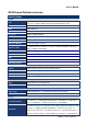
User’s Manual AX45Q specifications summary Specifications System CPU Intel® Q45 LGA775 socket for Intel® Core 2 Quad/Core 2 Duo Processors. Support Intel® next generation 45nm Multi-Core CPU FSB 1333/1066/800 MHz BIOS AMI 32Mb BIOS System Chipset Intel® Q45 GMCH/ICH10DO I/O Chipset Winbond W83627DHG-A Memory Four 240-pin DIMM sockets support up to 8 GB, DDR2 800 / 667 MHz Watchdog Timer Reset: 1 sec.~255 min. and 1 sec. or 1 min.
AX45Q Power connector Mechanical & Environment Power Type ATX mode Operating Temperature 0~60°C (32~140°F) Operating Humidity 0%~90% relative humidity, non-condensing Size (L x W) 12" x 9.6" (304.8 mm x 243.84 mm) * Specifications are subject to change without notice.
User’s Manual This chapter describes the motherboard features and the new technologies it supports.
AX45Q 1.1 Welcome! Thank you for buying an ® AX45Q motherboard! The motherboard delivers a host of new features and latest technologies, making it another standout in the long line of quality motherboards! Before you start installing the motherboard, and hardware devices on it, check the items in your package with the list below. 1.2 Package contents Check your motherboard package for the following items.
User’s Manual 1.3 Special features 1.3.1 Product highlights Latest processor technology The motherboard comes with a 775-pin surface mount Land Grid Array (LGA) socket designed for the Intel® Core 2 Duo, Intel® Core 2 Quad in the 775-land package. The motherboard supports the Intel® Core™ 2 Quad or Intel® Core™ 2 Duo processor with 1333/1066/800MHz Front Side Bus (FSB).
AX45Q for today’s and tomorrow’s business applications. The Intel Q45 Express Chipsets include support for the latest PC operating systems, including Windows Vista*. Intel® Stable Image Platform Program Reducing the variety of supported hardware greatly simplifies enterprise and small medium business PC management, which is reflected in a lower total cost of ownership. One critical element in reducing PC hardware variations involves deploying standardized desktop and laptop PC configurations.
User’s Manual BOM cost. Dual-channel DDR2 memory support Delivers up to 12.8 GB/s (DDR2 800 dual 6.4 GB/s) of bandwidth and 16 GB maximum supported memory size for faster system responsiveness and support of 64-bit computing. 5.1+2-CH high definition audio The onboard Realtek® ALC888 5.1+2-CH high-definition audio CODEC provides 192 KHz/ 24‑bit audio output, jack-sensing and re-stacking functions.
AX45Q 1.4 Before you proceed Take note of the following precautions before you install motherboard components or change any motherboard settings. y y y y y 14 AX45Q User’s Manual Unplug the power cord from the wall socket before touching any component. Use a grounded wrist strap or touch a safely grounded object or a metal object, such as the power supply case, before handling components to avoid damaging them due to static electricity Hold components by the edges to avoid touching the ICs on them.
User’s Manual 1.5 Motherboard overview Before you install the motherboard, study the configuration of your chassis to ensure that the motherboard fits into it. Make sure to unplug the power cord before installing or removing the motherboard. Failure to do so can cause you physical injury and damage motherboard components. 1.5.1 Placement Direction When installing the motherboard, make sure that you place it into the chassis in the correct orientation.
AX45Q 1.5.
User’s Manual 1.6 Central Processing Unit (CPU) The motherboard comes with a surface mount LGA775 socket designed for the Intel® Core™ 2 Quad/ Intel® Core™ 2 Duo processor in the 775-land package. y y y y Your boxed Intel® Core™ 2 Quad/ Intel® Core™ 2 Duo LGA775 processor package should come with installation instructions for the CPU, fan and heatsink assembly. If the instructions in this section do not match the CPU documentation, follow the latter.
AX45Q 2. Press the load lever with your thumb (A), then move it to the left (B) until it is released from the retention tab. To prevent damage to the socket pins, do not remove the PnP cap unless you are installing a CPU. 3. Lift the load lever in the direction of the arrow to a 135º angle. 4. Lift the load plate with your thumb and forefinger to a 100º angle (A), then push the PnP cap from the load plate window to remove (B). 5.
User’s Manual 6. Close the load plate (A), then push the load lever (B) until it snaps into the retention tab. The CPU fits in only one correct orientation. DO NOT force the CPU into the socket to prevent bending the connectors on the socket and damaging the CPU! The motherboard supports Intel® LGA775 processors with the Intel® Enhanced Memory 64 Technology (EM64T), Enhanced Intel SpeedStep® Technology (EIST), and Hyper-Threading Technology.
AX45Q 1.6.2 Installing the CPU Heatsink and Fan The Intel® Core™ 2 Quad/ Intel® Core™ 2 Duo LGA775 processor requires a specially designed heatsink and fan assembly to ensure optimum thermal condition and performance. z z z Install the motherboard to the chassis before you install the CPU fan and heatsink assembly. When you buy a boxed Intel® Core™ 2 Quad/ Intel® Core™ 2 Duo processor, the package includes the CPU fan and heatsink assembly.
User’s Manual 2. Push down two fasteners at a time in a diagonal sequence to secure the heatsink and fan assembly in place. 3. Connect the CPU fan cable to the connector on the motherboard labeled CPU_FAN. Do not forget to connect the CPU fan connector! Hardware monitoring errors can occur if you fail to plug this connector.
AX45Q 1.6.3 Uninstalling the CPU Heatsink and Fan To uninstall the CPU heatsink and fan: 1. Disconnect the CPU fan cable from the connector on the motherboard. 2. Rotate each fastener counterclockwise. 3. Pull up two fasteners at a time in a diagonal sequence to disengage the heatsink and fan assembly from the motherboard 4. Carefully remove the heatsink and fan assembly from the motherboard.
User’s Manual 5. Rotate each fastener clockwise to ensure correct orientation when reinstalling. The narrow end of the groove should point outward after resetting. (The photo shows the groove shaded for emphasis.
AX45Q 1.7 System memory 1.7.1 Overview The motherboard comes with two 240-pin Double Data Rate 2 (DDR2) Dual Inline Memory Modules (DIMM) sockets. A DDR2 module has the same physical dimensions as a DDR DIMM but has a 240-pin footprint compared to the 184-pin DDR DIMM. DDR2 DIMMs are notched differently to prevent installation on a DDR DIMM socket.
User’s Manual 1.7.2 Memory Configurations You may install 64 MB, 128 MB, 256 MB, 512 MB and 1 GB unbuffered ECC or non-ECC DDR DIMMs into the DIMM sockets using the memory configurations in this section. y y y y y y y IF you installed four 1GB memory modules, the system may detect less than 3GB of total memory because of address space allocation for other critical functions.
AX45Q 1.7.3 Installing a DIMM Make sure to unplug the power supply before adding or removing DIMMs or other system components. Failure to do so may cause severe damage to both the motherboard and the components. 1. Unlock a DIMM socket by pressing the retaining clips outward 2. Align a DIMM on the socket such that the notch on the DIMM matches the break on the socket. 3. Firmly insert the DIMM into the socket until the retaining clips snap back in place and the DIMM is properly seated.
User’s Manual 1.7.4 Removing a DIMM 1. Simultaneously press the retaining clips outward to unlock the DIMM. Support the DIMM lightly with your fingers when pressing the retaining clips. The DIMM might get damaged when it flips out with extra force. 2. Remove the DIMM from the socket.
AX45Q 1.8 Expansion slots In the future, you may need to install expansion cards. The following sub-sections describe the slots and the expansion cards that they support. Make sure to unplug the power cord before adding or removing expansion cards. Failure to do so may cause you physical injury and damage motherboard components. 1.8.1 Installing an Expansion Card 1. Before installing the expansion card, read the documentation that came with it and make the necessary hardware settings for the card. 2.
User’s Manual 1.8.3 PCI slots 1.8.4 PCI Express x16 The PCI slots support cards such as a LAN card, SCSI card, USB card, and other cards that comply with PCI specifications. The figure shows the type of LAN card that can be installed on a PCI slot. This motherboard supports PCI Express x16 graphic cards that comply with the PCI Express specifications. The figure shows a graphics card installed on the PCI Express x16 slot. 1.8.
AX45Q 1.9 Jumpers 1.9.1 Clear RTC RAM (CLRTC) This jumper allows you to clear the Real Time Clock (RTC) RAM in CMOS. You can clear the CMOS memory of date, time, and system setup parameters by erasing the CMOS RTC RAM data. The onboard button cell battery powers the RAM data in CMOS, which include system setup information such as system passwords. To erase the RTC RAM: 1. Turn OFF the computer and unplug the power cord. 2. Remove the onboard battery. 3.
User’s Manual 1.9.2 COM1/2 Voltage Select (JCOMPWR5, JCOMPWR6) This jumper allows you to select COM 1/2 Voltage power. 1.9.3 RS232/422/485 Select (JSETCOM1, JSETCOM2) This jumper allows you to select RS232/422/485.
AX45Q 1.9.4 Intruder Select (CHASSIS1) This jumper allows you to select Intruder.
User’s Manual 1.10 Connectors 1.10.1 Rear panel connectors 1. PS/2 mouse port (green). This port is for a PS/2 mouse. 2. Serial connector. This 9-pin COM1 port is for serial devices. 3 & 4. LAN (RJ-45) port. This port allows Gigabit connection to a Local Area Network (LAN) through a network hub. Refer to the table below for the LAN port LED indications.
AX45Q 12. PS/2 keyboard port (purple). This port is for a PS/2 keyboard. 1.10.2 Internal connectors 1. Front panel audio connector (10-pin AAFP1) This connector is for a chassis-mounted front panel audio I/O module that supports either HD Audio or legacy AC’97 audio standard. It is recommended that you connect a high-definition front panel audio module to this connector to avail of the motherboard’s high‑definition audio capability.
User’s Manual 2. Serial Port connector (COM2) This connector is for a serial (COM) port. Connect the serial port module cable to this connector, then install the module to a slot opening at the back of the system chassis.
AX45Q 3. Fan Connectors (3-pin SYS_FAN, 3-pin, 4-pin CPU_FAN, CHA_FAN) The fan connectors support cooling fans of 350mA~740mA (8.88W max.) or a total of 1A~2.22A (26.64W max.) at +12V. Connect the fan cables to the fan connectors on the motherboard, making sure that the black wire of each cable matches the ground pin of the connector. Do not forget to connect the fan cables to the fan connectors. Insufficient air flow inside the system may damage the motherboard components.
User’s Manual 4. USB connector (10-1 pin USB45, USB67, USB89, USB1011) This connector is for USB 2.0 ports. Connect the optional USB module cable to any of these connectors, then install the module to a slot opening at the back of the system chassis. This USB connector comply with USB 2.0 specification that supports up to 480 Mbps connection speed.
AX45Q 5. ATX power connectors (20-pin EATXPWR, 4-pin ATX12V) These connectors are for ATX power supply plugs. The power supply plugs are designed to fit these connectors in only one orientation. Find the proper orientation and push down firmly until the connectors completely fit. y y y 38 AX45Q User’s Manual Do not forget to connect the 4-pin ATX +12 V power plug; otherwise, the system will not boot.
User’s Manual 6. Serial ATA connector (7-pin SATA1, SATA2, SATA3, SATA4, SATA5) These connectors are for the Serial ATA signal cables for Serial ATA hard disk drives. Install the Windows® 2000 Service Pack 4 or the Windows® XP Service Pack1 or later before using Serial ATA. 7. System panel connector (10-1 pin F_PANEL1) This connector supports several chassis-mounted functions. The system panel connector is color-coded for easy connection. Refer to the connector description below for details.
AX45Q ON or puts the system in SLEEP or SOFT-OFF mode depending on the BIOS settings. Pressing the power switch for more than four seconds while the system is ON turns the system OFF. y System Power LED connector (2-pin PWRLED) This 2-pin connector is for the system power LED. The system power LED lights up when you turn on the system power, and blinks when the system is in sleep mode.
User’s Manual 9. SPI Connector (7-pin SPI1) It is a point-to-point interface standard, allows network equipment designers to develop an array of next-generation multi-service switches and routers to support multi-service traffic with aggregate bandwidths up to OC-192 (10 Gb/s) and beyond, enabling them to dramatically increase system performance. 10.
AX45Q This chapter tells how to change the system settings through the BIOS Setup menus. Detailed descriptions of the BIOS parameters are also provided.
User’s Manual 2.1 Managing and updating your BIOS 2.1.1 1. Creating a bootable floppy disk Do either one of the following to create a bootable floppy disk. DOS environment a. Insert a 1.44MB floppy disk into the drive. b. At the DOS prompt, type format A:/S then press . Windows® XP environment a. Insert a 1.44 MB floppy disk to the floppy disk drive. b. Click Start from the Windows® desktop, then select My Computer. c. Select the 3 1/2 Floppy Drive icon. d.
AX45Q 2.2 BIOS setup program The main BIOS setup menu is the first screen that you can navigate. Each main BIOS setup menu option is described in this user’s guide. The Main BIOS setup menu screen has two main frames. The left frame displays all the options that can be configured. “Grayed-out” options cannot be configured. Options is blue can be. The right frame displays the key legend. Above the key legend is an area reserved for a text message.
User’s Manual Tab The key allows you to select setup fields. F1 The key allows you to display the General Help screen. Press the key to open the General Help screen. F10 The key allows you to save any changes you have made and exit Setup. Press the key to save your changes. ESC The key allows you to discard any changes you have made and exit the Setup. Press the key to exit the setup without saving your changes.
AX45Q 2.3 Main Setup When you first enter the Setup Utility, you will enter the Main setup screen. You can always return to the Main setup screen by selecting the Main tab. There are two Main Setup options. They are described in this section. The Main BIOS Setup screen is shown below. y System Time/System Date Use this option to change the system time and date. Highlight System Time or System Date using the keys. Enter new values through the keyboard.
User’s Manual 2.4 Advanced BIOS Setup Select the Advanced tab from the setup screen to enter the Advanced BIOS Setup screen. You can select any of the items in the left frame of the screen, such as SuperIO Configuration, to go to the sub menu for that item. You can display an Advanced BIOS Setup option by highlighting it using the keys. All Advanced BIOS Setup options are described in this section. The Advanced BIOS Setup screen is shown below. The sub menus are described on the following pages.
AX45Q 2.4.1 CPU Configuration Setting You can use this screen to select options for the CPU Configuration Settings. Use the up and down keys to select an item. Use the and keys to change the value of the selected option. A description of the selected item appears on the right side of the screen. The settings are described on the following pages. y Max CPUID Value Limit The choices of Max CPUID Value Limit are Disabled, and Enabled.
User’s Manual y Core Multi-Processing The item is to enable or disable the Core Multi-processing function. y Intel® SpeedStep™ tech The choices of Execute-Disable Bit Capability are Enabled, Disabled.
AX45Q 2.4.2 IDE Configuration Setting You can use this screen to select options for the IDE Configuration Settings. Use the up and down keys to select an item. Use the and keys to change the value of the selected option. A description of the selected item appears on the right side of the screen. The settings are described on the following pages. y Mirrored IDER Configuration The choices of Mirrored IDER configuration are Disabled, and Enabled.
User’s Manual y Primary/Secondary IDE Master/Slave, Third/Fourth IDE Master Select one of the hard disk drives to configure it. Press to access its the sub menu. The options on the sub menu are described in the following sections. y IDE Detect Time Out (Sec) Set this option to stop the AMIBIOS from searching for IDE devices within the specified number of seconds. Basically, this allows you to fine-tune the settings to allow for faster boot times.
AX45Q y AHCI Configuration - AHCI BIOS Support Enables for supporting AHCI BIOS. The choices are Enabled or Disabled. - AHCI CD/DVD Boot Time Out Select the time out value for detecting AHCI CD/DVD device(s).
User’s Manual 2.4.3 SuperIO Configuration You can use this screen to select options for the Super I/O settings. Use the up and down keys to select an item. Use the and keys to change the value of the selected option. The settings are described on the following pages. The screen is shown below. y Serial Port1 Address This option specifies the base I/O port address and Interrupt Request address of serial port 1. The Optimal setting is 3F8/IRQ4.
AX45Q port 1 or COM1 ports on computer systems use IRQ4 and I/O Port 3F8 as the standard setting. The most common serial device connected to this port is a mouse. If the system will not use a serial device, it is best to set this port to Disabled. y Serial Port2 Address This option specifies the base I/O port address and Interrupt Request address of serial port 2. The Optimal setting is 2F8/IRQ3. Option Description Disabled Set this value to prevent the serial port from accessing any system resources.
User’s Manual y Chassis Intrusion This item selects the chassis intrusion. The choices are Disabled or Enabled. y System Temperature This shows you the current temperature of system. y CPU Temperature This shows you the current CPU temperature. y CPU_FAN Speed This shows the current CPU FAN operating speed. y SYS_FAN Speed This shows the current System FAN operating speed. y CHA_FAN Speed This shows the current Chassis FAN operating speed.
AX45Q 2.4.5 ACPI Configuration You can use this screen to select options for the ACPI settings. Use the up and down keys to select an item. Use the and keys to change the value of the selected option. The settings are described on the following pages. The screen is shown below.
User’s Manual y Chipset ACPI Configuration This item allows you to set South Bridge ACPI Configuration. - High Performance Event Timer This item allows you to enable or disable the High Performance Event Timer.
AX45Q 2.4.6 APM Configuration You can use this screen to select options for the APM settings. Use the up and down keys to select an item. Use the and keys to change the value of the selected option. The settings are described on the following pages. The screen is shown below. y Power Management/APM This item allows you to set APM to Enabled or Disabled. y Restore on AC Power Loss This item allows you to set AC Power Loss to Power Off, Power On, or Last State.
User’s Manual y Resume On PME# Disable or Enable PME to generate a wake event. y Resume On PCIE WAKE# Disable or Enable PCIE generate a wake event. y Resume RTC Alarm Disable or Enable RTC to generate a wake event. 2.4.7 Intel Danbury (DT) Configuration You can use this screen to select options for the Intel Danbury (DT) settings. Use the up and down keys to select an item. Use the and keys to change the value of the selected option. The settings are described on the following pages.
AX45Q 2.4.8 Intel TXT (LT) Configuration You can use this screen to select options for the Intel TXT (LT) settings. Use the up and down keys to select an item. Use the and keys to change the value of the selected option. The settings are described on the following pages. The screen is shown below. y Intel TXT Initialization The Choices are enabled or disabled the Intel TXT initialization.
User’s Manual 2.4.9 Intel VT-d Configuration You can use this screen to select options for the Intel VT-d settings. Use the up and down keys to select an item. Use the and keys to change the value of the selected option. The settings are described on the following pages. The screen is shown below. y Intel VT-d The Choices are enabled or disabled the Intel VT-d.
AX45Q 2.4.10 Trusted Computing You can use this screen to select options for the Intel Trusted Computing settings. Use the up and down keys to select an item. Use the and keys to change the value of the selected option. The settings are described on the following pages. The screen is shown below. y TCG/TPM SUPPORT Enable or disable TPM TCG (TPM 1.1/1.2) support in BIOS. y Execute TPM Command The choices are “Don’t Change” / “Disabled” / “Enabled”.
User’s Manual 2.5 Advanced PCI/PnP Settings Select the PCI/PnP tab from the setup screen to enter the Plug and Play BIOS Setup screen. You can display a Plug and Play BIOS Setup option by highlighting it using the keys. All Plug and Play BIOS Setup options are described in this section. The Plug and Play BIOS Setup screen is shown below. 2.5.1 Clear NVRAM This item is to clear NVRAM during system boot. The choices are No or Yes. 2.5.
AX45Q specifications. It allows the BIOS to configure all the devices in the system. This is the default setting. Yes The Yes setting allows the operating system to change the interrupt, I/O and DMA settings. Set this option if the system is running Plug and Play aware operating systems. 2.5.3 PCI Latency Timer Set this value to allow the PCI Latency Timer to be adjusted. This option sets the latency of all PCI devices on the PCI bus. The default setting is 64.
User’s Manual card’s manual first, before modifying the default settings in the BIOS. 2.5.6 PCI IDE BusMaster Set this value to allow or prevent the use of PCI IDE busmastering. The setting is Disabled. Option Description Disabled Set this value to prevent PCI busmastering. This is the default setting. Enabled This option specifies that the IDE controller on the PCI local bus has mastering capabilities. 2.5.7 OffBoard PCI/ISA IDE Card Set this value to allow the OffBoard PCI/ISA IDE Card to be selected.
AX45Q setting. 2.5.8 IRQ Set this value to allow the IRQ settings to be modified. The default setting is available. Interrupt Option Description IRQ3 IRQ4 IRQ5 IRQ7 IRQ9 IRQ10 IRQ11 IRQ14 IRQ15 This setting allows the specified IRQ to be used by a PCI/PnP device. This is the default setting. Available Reserved This setting allows the specified IRQ to be used by a legacy ISA device. 2.5.9 DMA Set this value to allow the DMA setting to be modified. The default setting is Available.
User’s Manual 2.6 Boot Setting Configuration Select the Boot tab from the setup screen to enter the Boot Setup screen. You can display a Boot Setup option by highlighting it using the keys. All Boot BIOS Setup options are described in this section. The Boot BIOS Setup screen is shown below.
AX45Q 2.6.1 Boot Settings Configuration You can use this screen to select options for the Boot settings. Use the up and down keys to select an item. Use the and keys to change the value of the selected option. The settings are described on the following pages. The screen is shown below. y Quick Boot The default setting is Enabled. Option Description Disabled Set this value to allow the BIOS to perform all POST tests.
User’s Manual Option Description Disabled Set this value to allow the computer system to display the POST messages. Enabled Set this value to allow the computer system to display the OEM logo. This is the default setting. y Bootup Num-Lock Set this value to allow the Number Lock setting to be modified during boot up. The default setting is On. Option Description Off This option does not enable the keyboard Number Lock automatically.
AX45Q during memory initialization. If Quiet Boot is enabled, the Hit “DEL” message will not display. Enabled This allows the to display Hit Del to Enter Setup during memory initialization. This is the default setting. 2.6.2 Boot Device Priority Use this screen to specify the order in which the system checks for the device to boot from. To access this screen, select Boot Device Priority on the Boot Setup screen and press .
User’s Manual 2.6.3 Hard Disk Drives Use this screen to view the hard disk drives in the system. To access this screen, select Hard disk drives on the Boot Setup screen and press . The following screen displays examples of hard disk drives: y 1st Drive This item specifies the boot sequence from the available device.
AX45Q 2.7 Security Setup Select Security Setup from the Setup main BIOS setup menu. All Security Setup options, such as password protection and virus protection, are described in this section. To access the sub menu for the following items, select the item and press : y Change Supervisor Password The Security Setup screen is shown below. The sub menus are documented on the following pages. 2.7.1 Change Supervisor Password This item indicates whether a supervisor password has been set.
User’s Manual 2.8 Chipset Setup Select the Chipset tab from the setup screen to enter the Chipset BIOS Setup screen. You can select any of the items in the left frame of the screen, such as CPU Configuration, to go to the sub menu for that item. You can display a Chipset BIOS Setup option by highlighting it using the keys. All Chipset BIOS Setup options are described in this section. The Chipset BIOS Setup screen is shown below.
AX45Q 2.8.1 North Bridge Configuration You can use this screen to select options for the North Bridge Configuration. Use the up and down keys to select an item. Use the and keys to change the value of the selected option. Note: The North Bridge Configuration setup screen varies depending on the supported North Bridge chipset. y Memory Remap Feature Set this value to allow the Memory Remap Feature to be modified. The default setting is Enabled.
User’s Manual y Initate Graphic Adapter This item selects which graphics controller to use as the primary boot device. The options are IGD, PCI/IGD, PCI/PEG, PEG/IGD, PEG/PCI. The default setting is PEG/PCI. y IGD Graphics Mode Select This item selects the amount of system memory used by the internal graphics device. The choices are Disabled, Enabled 32MB, Enabled 64MB, and Enabled 128MB. y PEG Port The choices are Auto or Disabled.
AX45Q - DVMT/Fixed Memory Size Specify the size of DVMT/system memory to allocate for video memory. 2.8.2 South Bridge Configuration You can use this screen to select options for the South Bridge Configuration. South Bridge is a chipset on the motherboard that controls the basic I/O functions, USB ports, audio functions, modem functions, IDE channels, and PCI slots. Use the up and down keys to select an item. Use the and keys to change the value of the selected option.
User’s Manual y USB Port Configure The choices are 6x6 USB Ports, and 8x4 USB Ports. y OnBoard LAN1 Options are “Enabled” and “Disabled”. Select “Disabled” if you don’t want to use onboard LAN controller1. y OnBoard LAN2 Options are “Enabled” and “Disabled”. Select “Disabled” if you don’t want to use onboard LAN controller2. y OnBoard LAN Boot ROM Options are “Enabled” and “Disabled”. Select “Disabled” if you don’t want to use onboard LAN Boot Rom. y HDA Controller Options are “Enabled” and “Disabled”.
AX45Q 2.9 Exit Menu Select the Exit tab from the setup screen to enter the Exit BIOS Setup screen. You can display an Exit BIOS Setup option by highlighting it using the keys. All Exit BIOS Setup options are described in this section. The Exit BIOS Setup screen is shown below.
User’s Manual 2.9.1 Save Changes and Exit When you have completed the system configuration changes, select this option to leave Setup and reboot the computer so the new system configuration parameters can take effect. Select Exit Saving Changes from the Exit menu and press . Save Configuration Changes and Exit Now? [Ok] [Cancel] appears in the window. Select Ok to save changes and exit.
AX45Q 2.9.2 Discard Changes and Exit Select this option to quit Setup without making any permanent changes to the system configuration. Select Exit Discarding Changes from the Exit menu and press . Discard Changes and Exit Setup Now? [Ok] [Cancel] appears in the window. Select Ok to discard changes and exit.
User’s Manual 2.9.3 Discard Changes Select Discard Changes from the Exit menu and press . Discard Changes ? [Ok] [Cancel] appears in the window. Select Ok to discard changes.
AX45Q 2.9.4 Load Setup Default Automatically sets all Setup options to a complete set of default settings when you Select this option. The Optimal settings are designed for maximum system performance, but may not work best for all computer applications. In particular, do not use the Optimal Setup options if your computer is experiencing system configuration problems. Select Load Setup Defaults from the Exit menu and press . Select Ok to load optimal defaults.