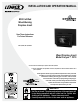
INSTALLATION AND OPERATION MANUAL EPA Certified Wood-Burning Fireplace Insert Save These Instructions For Future Reference P/N 775,213M, Rev. B, 02/2010 Wood Fireplace Insert Model Canyon™ C310 A French manual is available upon request. Order P/N 775,213CF. Ce manuel d’installation est disponible en francais, simplement en faire la demande. Numéro de la pièce 775,213CF. US These appliances must be properly installed and operated in order to prevent the possibility of a house fire.
CONGRATULATIONS! Positive Flue Connection............................................................... 10 Insert Pre-Installation Preparation................................................ 11 When you purchased your new wood-burning fireplace insert, you joined the ranks of thousands of individuals whose answer to their home heating needs reflects their concern for aesthetics, efficiency and our environment.
IMPORTANT SAFETY AND WARNIING INFORMATION READ THIS MANUAL IN ITS ENTIRETY AND UNDERSTAND THESE RULES TO FOLLOW FOR SAFETY. 1. When this room heater is not properly installed, a house fire may result. To reduce the risk of fire, follow the installation instructions. Contact local building or fire officials about restrictions and installation inspection requirements in your area. 2. Wear gloves during installation to avoid injury from sharp edges on the fireplace insert and/or its parts. 3.
Testing Information This manual describes the installation and operation of the Canyon™ C310 non-catalytic wood heaters. These heaters meet the U.S. Environmental Protection Agency’s emissions limits for wood heaters sold on or after July 1, 1990. This heater has been developed, tested and constructed in accordance with the requirements of UL 1482, ULC S628 and HUD standards and is listed by OMNI Test Laboratories, Portland, OR. It has been approved for residential and alcove installations.
Negative Pressure Warning This appliance is not designed to be operated in a negative pressure. In very airtight homes with large kitchen exhaust fans, furnace cold air returns, fresh air exchange systems and any other air system in close proximity to the heating appliance may create a negative pressure in the same room as the heating appliance. This can create dangerous back drafting of the stove and chimney joints, drawing combustion by-products into the home.
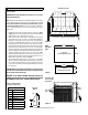
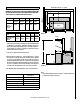
Brick Installation Firebox Brick Layout Canyon™ C310 26 B CAUTION: Wear gloves during brick installation in case of sharp edges behind the stove. Note: Installation of the baffle boards and baffle blankets are easier when you can still access the flue outlet, (before connecting the flue vent). Be sure the baffle blankets are placed flat on the baffle boards so as not to block exhaust flow to the flue.
Maximum Mantel Depth = 9” (229mm) Required Clearances COMBUSTIBLE MANTEL WARNING: BE ABSOLUTELY SURE THE DISTANCE BETWEEN THE HEATER AND THE SURFACE OF ANY COMBUSTIBLE CONSTRUCTION IS NOT LESS THAN SHOWN ON THIS PAGE.
Using the r formula: Hearth Protection The hearth and/or floor protection must be a thermally rated non-combustible hearth/floor protector meeting or exceeding a thermal rating of k=.84 or equivalent with a listed thickness of 3/4" (19mm) minimum in USA and Canada. The covering must extend 24” (610mm) in front of the heater and 8” (200mm) to either side (measured from door opening in the USA and measured from the side of the unit in Canada).
Chimney Requirements The Canyon™ C310 inserts are approved for use in masonry fireplaces built to UBC Chapter 37 or equivalent with a minimum 30-1/2” (775) width opening at the front of the fireplace. 1. READ ENTIRE INSTALLATION INSTRUCTIONS. 2. Check all REQUIRED CLEARANCES as specified in the previous section (Page 7) of this installation instruction booklet. 3. Wear gloves during installation in case of sharp edges on the stove and it’s parts.
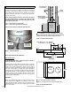
POSITIVE FLUE CONNECTION A full chimney liner is recommended A positive flue connection is providing a seal between the vent pipe or liner and the existing fireplace chimney for the purpose of preventing room air passage to the chimney cavity of the fireplace. There are different approved methods to achieve this. See Direct Connect Positive Flue Connection on this page. When creating a positive flue connection, a positive flue connector ring kit is required (sold separately - see Figure 7).
Insert Pre-Installation Preparation Install the two 3” (76 mm) long bolts (with the head up) through the nuts attached to the insert on the lower rear corner of each side. This will allow you to level the insert when placed into the fireplace. Measure from the front of the top surround mount to the center of the flue. Determine if there is an alignment problem in connecting a liner from the chimney to the insert’s flue.
Operating Hints Starting and Maintaining a Fire 1. Burn only dry, well-seasoned wood for maximum heat output. In some states it is illegal to burn wet wood or anything other than clean, dry wood products. 2. Your fireplace insert is designed to operate with the door closed! Operate only with the door shut tightly at all times except when loading wood and possibly on start up to establish a draft. Never leave the unit unattended while the front door is slightly opened. 3.
BLOWER OPERATION Blower Operation The blower can be operated manually or automatically (blower will turn on when the insert is hot and turn off when the insert is cool). The rocker switch on the control panel allows you to select between manual operation or automatic operation as follows (see Figure 10): MANUAL OPERATION: Turn rocker switch to the manual position (up) and adjust rheostat knob to the desired speed.
Operating Techniques and Hints Achieving Clean, Long Burns Recent developments in wood-burning technology have made wood-burning a cleaner and more convenient way to heat your home. Overall efficiency in a wood-burning appliance is a combination of combustion efficiency and heat transfer efficiency. Whether heating your entire home, or just a room or two, your understanding of how to best operate your stove or insert will enhance its overall efficiency and performance.
Maintenance Clean Glass Door HINGES: If door hinges need lubricating, use an anti-seize compound (never use oil) available from your Lennox Hearth Products dealer. Door Latch: If your door latch fails to latch tightly and the gasket is in good condition, place a length of pipe (cheater bar) over the inside portion of the door handle and bend slightly toward the door until the proper adjustment is obtained. If the door handle does not close easily, apply high temperature anti-seize to the striker.
Troubleshooting 16 Problem Solution POOR DRAFT: Extend chimney in length or have the chimney realigned to the proper size flue. Oversized chimneys normally have poor drafts. Remember, the stoves’ draft depend solely on the natural draft of the chimney (See Drafting section on Page 4). If your stove is not drafting properly, your chimney is the problem. All stoves are thoroughly tested to ensure proper draft with the correct size chimney flue.
Do’s and Don’t DO NOT: Install or operate this stove before reading this manual. DO NOT: Close the draft beyond the point at which the flames are completely extinguished. DO NOT: Open the stove door without fully opening the draft first. DO NOT: Burn driftwood or wood that has been in salt water. This includes some mill ends and scrap lumber that has been floated in salt water on the way to the mill. (This will void your warranty). DO NOT: Handle the Nickel or Gold faceplate unnecessarily.
Replacement Parts - Model C310 Contact an Authorized Lennox Hearth Products dealer to obtain any of these parts. Never use substitute materials. Use of non-approved parts can result in poor performance and safety hazards.
Replacement Parts - Model C310 33 34 48 47 36 36 46 37 35 37 39 45 39 39 39 40 40 38 40 38 38 38 38 38 41 40 38 38 38 38 38 38 38 38 42 38 44 38 41 42 38 43 NOTE: DIAGRAMS & ILLUSTRATIONS ARE NOT TO SCALE.
Replacement Parts - Model C310 Door Parts 1 2 3 11 8 4 4 5 9 6 7 10 Blower Parts 29 15 17 16 19 32 18 20 NOTE: DIAGRAMS & ILLUSTRATIONS ARE NOT TO SCALE.
BLOWERS Accessories - Model C310 SURROUND PANELS / TOP AND SIDES (REQUIRED) Cat. No. Model Description 29” x 40”: 71038 WFPT0740-L 71031 WFPS0621 71039 WFPT0748-L 71032 WFPS1021 Blower Insert Nickle H7915 WLINS-BLWR-BN-SS Blower Insert Br-nkl H7916 WLINS-BLWR-BG-SS Blower Insert Br-gold MISC. PARTS Paint Gold (1/2 Pint) Paint Nickel (1/2 Pint) Top Surround 7-1/2” x 48” 70K99 TSPK-B Touch-Up Paint , Metallic Black, 12 oz.
SAFETY / LISTING LABEL 22
NOTES 23
Warranty Your wood appliance is covered by a limited warranty (provided with the appliance). Please read the warranty to be familiar with its coverage. 3. The part number. 4. The description of the part. 5. The quantity required. 6. The installation date of the appliance. Retain this manual. File it with your other documents for future reference. If you encounter any problems or have any questions concerning the installation or application of this system, please contact your dealer.