
Outdoor Fireplace User Manual


16
NOTE: DIAGRAMS & ILLUSTRATIONS NOT TO SCALE.
Printed in U.S.A. © 2006 by Lennox Hearth Products
P/N 850,034M REV. D 04/2009
Lennox Hearth Products reserves the right to make changes at any time, without notice, in design,
materials, specifications, prices and also to discontinue colors, styles and products.
Consult your local distributor for fireplace code information.
1110 West Taft Avenue • Orange, CA 92865
Figure 21
Figure 20
Figure 22
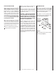
Note: If the ignitor is damaged, a replace-
ment kit is available, order Catalog Number
87L54.
Electronic Appliances
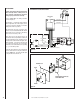
Step 4. Dexen Electronic Valves - See Figure
20 and the instructions provided with the kit.
Remove and discard the two pressure regulator
mounting screws. Remove the pressure regula-
tor and diaphragm. Discard all removed compo-
nents. Ensure the rubber gasket installed on
the back of the replacement pressure regulator
is properly positioned. Install the new pressure
regulator using the new screws supplied with the
kit. Tighten screws to 25 In. lb. torque.
Note: Natural gas regulators are identified with a
blue dot. Propane regulators have a red dot.
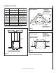
Step 5. See Figure 21 and replace the pilot
orifice as follows: Remove pilot hood assembly
by grasping the hood and pulling the assembly
straight up. Under the hood is the pilot orifice.
With caution and using a magnetic screwdriver,
undo the pilot orifice and remove it from the
assembly. Carefully replace the orifice with the
one provided with the kit. Press the pilot hood
back over the assembly. The orientation should
be aligned as shown in Figure 21. Exercise
extreme care to prevent damage to or break-
age of the ignitor assembly.
Note: Propane pilot orifices are identified with a
countersink in the head. Natural gas orifices do
not have this countersink. See Figure 21.
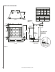
Step 6. (Refer to Figure 19 on page 15 )
A. Remove the orifice from the manifold with
a 1/2" deep throat socket. See the following
table for orifice sizes for natural and propane
models. Figure 22 illustrates the orifice.
Use pipe joint compound or Teflon tape on all
pipe fittings before installing (ensure propane
resistant compounds are used in propane ap-
plications, do not use pipe joint compounds
on flare fittings).
B. Retrieve the burner and slide the venturi tube
over the orifice. Secure the burner in place with
the clip shown in Figure 19.
Step 7. Reassemble the remaining components
by reversing the procedures outlined in the
preceding steps.
ELECTRONIC PILOT
Pilot
Hood
Sensor
Ignitor
PROPANE
NATURAL
.oNledoM
ezisecifirO
laruta naporP
GDO63E
82#
.1405)
0(
GDO24E
82#
.1405)
0(
74#
.0785)
0(
74#
.0785)
0(
N
e
NOTE: DIAGRAMS & ILLUSTRATIONS NOT TO SCALE.
Pilot Stage
Terminal
Pressure-Tap
(Inlet)
Pilot Gas
Outlet
Supply
Gas
Inlet
Pressure-Tap
(Manifold)
Burner Stage
Terminal
Ground
(TP)
PILOT
OUT
VENT
LO
TH
TP
TH
TP
HI
IN
IN
Gas Outlet
To Burner
Regulator
Mounting Screw