
Outdoor Fireplace User Manual

NOTE: DIAGRAMS & ILLUSTRATIONS NOT TO SCALE.
7
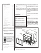
Right Side
Front Corner
Of Fireplace
Framing
3-3/4"
(95 mm)
1-3/4"
(44 mm)
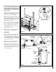
Figure 5
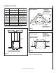
Note: An addiional inlet has been provided on
the left side (see Figure 6 ).
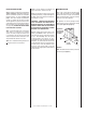
Step 2. Level the firebox by checking the top
edge of the firebox. Shim if necessary.
Step 3. The fireplace should be secured to the
side framing members, using the full length nail-
ing flange located on both sides of the fireplace.
Use 8d nails, or screws.
IMPORTANT: UNDER NO CIRCUMSTANCES
SHALL THE FIREBOX TOP SPACERS BE RE-
MOVED OR MODIFIED. THE HEADER MAY BE
IN DIRECT CONTACT WITH THE TOP SPACERS
BUT MUST NOT BE SUPPORTED BY THEM OR
NOTCHED TO FIT AROUND THEM.
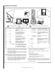
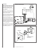
Step 4. Identify the desired location for the
battery pack/ON/OFF switch junction box.
This should be easily accessible and connivent
for use. Avoid installing where the opening
could be blocked by snow, bushes, etc. Also,
considerations need to be made to avoid water
infiltration. The electrical junction box must be
positioned within range of the electrical umbili-
cal cord (9 feet). Route the umbilical cord to
the box to ensure proper length. Secure the
umbilical cord per appropriate local and national
electrical codes.
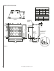
FIREPLACE INSTALLATION
Step 1. Frame these appliances as illustrated in
Figures 7 through 9. All framing details must
allow for a minimum clearance to combustible
framing members, as shown in Figure 4 on
page 5. Also refer to Fireplace Specifications
on Page 8. Headers may be in direct contact
with the appliance top spacers but must not be
supported by them or notched to fit around them.
All construction above the appliance must be
self supporting. DO NOT USE THE APPLIANCE
FOR STRUCTURAL SUPPORT.
Note: The framed depth from a framed wall,
must always be measured from a finished
surface. If a wall covering such as durrock is
to be attached to the rear wall, then the depth
must be measured from the wall surface. It is
important that this dimension be exact.
Note: Non-combustible framing members are
not required, but are recommended.
ROUTING GAS LINE
Route a 1/2" (13 mm) gas line along the inside
of the right side framing as shown in Figure
5. Gas lines must be routed, constructed and
made of materials that are in strict accordance
with local codes and regulations.
All appliances are factory-equipped with a
flexible gas line connector and 1/2 inch shutoff
valve. (See Figure 12 on page 11).