
Gas Heater User Manual

INSTALLATION - MODEL L20 DVF-2 ONLY
PAGE 9
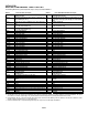
Direct Vent Retrofit Of Existing Chimney System - An existing Class-A (wood-burning) Metal Chimney or Masonry Chimney can be
converted to a direct vent system. Use one of the following chimney conversion kits listed below. Have the existing chimney system
inspected by a professional prior to the conversion. If using Simpson Dura-Vent brand liner kit, see “IMPORTANT” note at the top of
page 8. The chimney conversion should not be applied to the portion of the vent system that is in the room of the appliance. Use only
Co-Axial direct vent pipe (4” inner pipe, 6 5/8” outer pipe as listed on page 8) from the appliance to the retro-connector into converted
flue system. Adhere to all specifications shown on pages 6 and 7 regarding clearances to combustibles, vertical and horizontal vent
length minimums and maximums, etc. Read all instructions in this manual and provided by vent manufacturer with kit carefully before
starting the installation. Failure to follow the instructions may create a fire or other safety hazard, and will void the warranty.
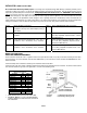
Model # Brand: SECURITY / Description Model # Brand: SIMPSON DURA-VENT / Description
SV4MCK Masonry Chimney Conversion Kit –Vertical term. Cap,
cap adapter, masonry cover, black adapter (to flex), 2
gear clamps
934 Masonry Chimney Conversion Kit
SV4CCK1 Factory Built Chimney Conversion Kit – for 6” I.D., 1”
insulation.
931 Factory Built Chimney Conversion Kit A – for 6”
I.D.; Only compatible w/specific brands – Contact
Vent Manufacturer
SV4CCK2 Factory Built Chimney Conversion Kit – for 7” I.D., 1”
insulation; 8” I.D., 1” insulation; 6” I.D., 2” insulation.
932 Factory Built Chimney Conversion Kit B – for 6”, 7”
& 8” I.D.; Only compatible w/specific brands –
Contact Vent Manufacturer
SV4CCK3 Factory Built Chimney Conversion Kit – for 10” I.D., 1”
insulation; 7” I.D., 2” insulation; 8” I.D., 2” insulation.
933 Factory Built Chimney Conversion Kit C – for 7” &
8” I.D.; Only compatible w/specific brands – Con-
tact Vent Manufacturer
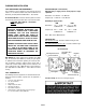
MODELS L20 BF-2 AND L20 DVF-2
VERTICAL VENT TERMINATION REQUIREMENTS
These instructions should be used as a guideline and do not supersede local codes in any way. Install vent according to local codes,
these instructions, the current National Fuel Gas Code (ANSI-Z223.1) in the USA or the current standards of CAN/CGA-B149.1 and -
B149.2 in Canada.
Terminate multiple vent terminations according to the installation codes listed above.
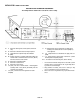
Terminate single vent caps relative to building components according to the following chart & illustration. The vent/air intake termina-
tion clearances above the high side of an angled roof is as shown in the following chart:
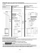
• Venting terminals shall not be recessed into a wall or siding.
• Ref. NFPA 54 / ANSI Z223.1, 7.6, fig. 13: Gas Vent Termination
locations for listed Caps, 12 inches or less in size, at least 8 feet
from a vertical wall.
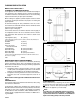
Termination Heights For Vents
Above Flat or Sloped Roofs
Roof Pitch Feet Meters
Flat to 6/12 1 0.3
6/12 to 7/12 1.25 0.38
7/12 to 8/12 1.5 0.46
8/12 to 9/12 2 0.61
9/12 to 10/12 2.5 0.76
10/12 to 11/12 3.25 0.99
11/12 to 12/12 4 1.22
12/12 to 14/12 5 1.52
14/12 to 16/12 6 1.83
16/12 to 18/12 7 2.13
18/12 to 20/12 7.5 2.29
20/12 to 21/12 8 2.44
Horizontal Overhan
g
2 Ft. Min.
2 Ft. Min.
Lowest
Discharge
Opening
V
en
t
Termination
* H
Storm
Collar
Flashing
1 inch (25.4 mm) Minimum
Clearance to Combustibles
Concentric
Vent Pipe
X
12
Roof Pitch is X/12
* H = Minimum height from roof to
lowest discharge opening of vent.