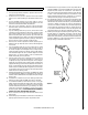
INSTALLATION AND OPERATION MANUAL Free-Standing EPA Certified Wood-Burning Stoves Save These Instructions For Future Reference P/N 775,216M, Rev. E, 02/2010 Wood Stoves Model Legacy™ S260 T-Top A French manual is available upon request. Order P/N 775,216CF. Ce manuel d’installation est disponible en francais, simplement en faire la demande. Numéro de la pièce 775,216CF. US These appliances must be properly installed and operated in order to prevent the possibility of a house fire.
CONGRATULATIONS! Installation Clearances Diagrams.................................................... 7 Leg and Heatshield Installation....................................................... 8 When you purchased your new wood stove, you joined the ranks of thousands of individuals whose answer to their home heating needs reflects their concern for aesthetics, efficiency and our environment.
IMPORTANT SAFETY AND WARNIING INFORMATION read THIS MANUAL IN ITS ENTIRETY and understand these Rules to follow for safety. 1. When this room heater is not properly installed, a house fire may result. To reduce the risk of fire, follow the installation instructions. Contact local building or fire officials about restrictions and installation inspection requirements in your area. 2. Wear gloves during installation to avoid injury from sharp edges on the stove and/or its parts. 3.
Testing Information This manual describes the installation and operation of the Legacy™ S260 non-catalytic wood heaters. These heaters meet the U.S. Environmental Protection Agency’s emissions limits for wood heaters sold on or after July 1, 1990. This heater has been developed, tested and constructed in accordance with the requirements of UL 1482, ULC S627 and HUD standards and is listed by OMNI Test Laboratories, Portland, OR. It has been approved for residential, mobile home and alcove installations.
Negative Pressure Warning This appliance is not designed to be operated in a negative pressure. In very airtight homes with large kitchen exhaust fans, furnace cold air returns, fresh air exchange systems and any other air system in close proximity to the heating appliance may create a negative pressure in the same room as the heating appliance. This can create dangerous back drafting of the stove and chimney joints, drawing combustion by-products into the home.
Clearances to Combustibles WARNING: BE ABSOLUTELY SURE THE DISTANCE BETWEEN THE HEATER AND THE SURFACE OF ANY COMBUSTIBLE CONSTRUCTION IS NOT LESS THAN SHOWN IN THE DIAGRAMS ON PAGE 7. Floor Protection USA - The floor in front and under the heater must be protected with a minimum of 3/8” thick noncombustible material. The covering must extend 16” in front of the door opening of the heater and 8” to either side of the door opening and 5-1/2” to the rear or to the wall, whichever is smaller.
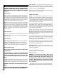
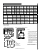
Installation Clearances - Refer to Diagrams A, B and C A B (1) C D (1) E† F (1,4) G (4) H (2) 6” Single Wall PIPE INSTALLATION Residential 18” (450mm) 15-1/2” (394mm) 26” (660mm) 16” (406mm) 8” 200mm 11” (279mm) 21” (533mm) USA-37-1/4” CAN-1200mm 6” Double Wall Residential or Alcove or Mobile Home* 12” (305mm) 9-1/2" (241mm) 23” (584mm) 13” (330mm) 8” 200mm 11” (279mm) 21” (533mm) USA-37-1/4” CAN-1200mm 8” Single Wall Residential 23” (584mm) 20-1/2” (521mm) 28” (711mm) 18”
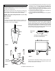
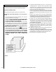
Leg and Heatshield Installation Residential and Mobile Homes - Bolting down and grounding of stove are required only in mobile homes. Open all cartons, if any and remove the contents upon receipt and check for any damaged or missing parts. If there is hidden damage, notify your freight company or Lennox Hearth Products dealer immediately. 3. First, screw the threaded rods into the holes at the four corners on the bottom of the stove.
Stove Installation 1. 2. 3. 4. 5. 6. 7. 8. 9. 10. 11. 12. 13. If not previously installed, install floor protection and move the heater into the desired location. Position the stove on your floor protection in the exact location where it is to be located, making sure all minimum clearances are met. If you are installing outside air on your stove, mark a 4” circle on the floor protection just below the oblong ring. When cut out, this hole will accommodate the flexible outside air tube.
Pedestal Installation (For ash drawer pedestal see instructions included with pedestal) Residential and Mobile Homes (Bolting down and grounding are required only in mobile homes) CAUTION: Wear gloves during installation in case of sharp edges on the stove. 1. Remove the heater from the carton, if packaged, upon receipt and check for any damaged or missing parts. 2. Carefully put the stove on pedestal with the open end of the pedestal facing the rear.
Post Installation Checks 1. Check that all chimney pipe joints are securely fastened. 2. Check that the heater is securely fastened to the floor (if applicable). FOR YOUR OWN PROTECTION AND INSURANCE PURPOSES, HAVE YOUR CHIMNEY AND CONNECTOR PIPE INSTALLATION INSPECTED BY YOUR LOCAL BUILDING CODE AUTHORITY OR FIRE MARSHAL BEFORE STARTING A FIRE IN YOUR STOVE. NOTIFY YOUR INSURANCE COMPANY. 3. Make sure the intake vent has clear access to outside air (if applicable). 4.
Brick Installation CAUTION: Wear gloves during brick installation in case of sharp edges inside the stove. Note: Installation of the baffle boards and insulating blanket is easier when you can still access the flue outlet (before connecting flue vent). Be sure the baffle blanket is placed flat on the baffle boards so as not to block exhaust flow to the flue. Use a ruler or piece of kindling to reach over the baffle blanket to be sure it is completely flat on top of the baffle bricks. 1.
Starting and Maintaining a Fire Operating Hints 1. Burn only dry, well-seasoned wood for maximum heat output. In some states it is illegal to burn wet wood or anything other than clean, dry wood products. 2. Your stove is designed to operate with the door closed! Operate only with the door shut tightly at all times except when loading wood and possibly on start up to establish a draft. Never leave the unit unattended while the front door is slightly opened. 3.
BLOWER OPERATION Blower Operation The blower can be operated manually or automatically (blower will turn on when the stove is hot and turn off when the stove is cool). The rocker switch on the control panel allows you to select between manual operation or automatic operation as follows (see Figure 12): MANUAL OPERATION: Turn rocker switch to the “MANUAL” position and adjust rheostat knob to the desired speed.
Operating Techniques and Hints Recent developments in wood burning technology have made wood burning a cleaner and more convenient way to heat your home. Overall efficiency in a wood burning appliance is a combination of combustion efficiency and heat transfer efficiency. Whether heating your entire home, or just a room or two, your understanding of how to best operate your stove or insert will enhance its overall efficiency and performance.
Cleaning Glass Maintenance Door Hinges: If door hinges need lubricating, use an anti-seize compound (never use oil) available from your Lennox Hearth Products dealer. Door Latch: If your door latch fails to latch tightly and the gasket is in good condition, place a length of pipe (cheater bar) over the inside portion of the door handle and bend slightly toward the door until the proper adjustment is obtained. If the door handle does not close easily, apply high temperature anti-seize to the striker.
Troubleshooting Problem Solution POOR DRAFT: Extend chimney in length or have the chimney realigned to the proper size flue. Oversized chimneys normally have poor drafts. Remember, the stoves’ draft depend solely on the natural draft of the chimney (See Drafting section on Page 4). If your stove is not drafting properly, your chimney is the problem. All stoves are thoroughly tested to ensure proper draft with the correct size chimney flue.
Do’s and Don’ts DO NOT: Install or operate this stove before reading this manual. DO NOT: Close the draft beyond the point at which the flames are completely extinguished. 18 DO NOT: Open the stove door without fully opening the draft first. DO NOT: Burn driftwood or wood that has been in salt water. This includes some mill ends and scrap lumber that has been floated in salt water on the way to the mill. (This will void your warranty). DO NOT: Handle the Nickel or Gold faceplate unnecessarily.
Replacement Parts - Model S260 Contact an Authorized Lennox Hearth Products dealer to obtain any of these parts. Never use substitute materials. Use of non-approved parts can result in poor performance and safety hazards. FRONT DOOR PARTS LIST FSB BLOWER PARTS Item # Cat.
Replacement Parts - Model S260 20 NOTE: DIAGRAMS & ILLUSTRATIONS ARE NOT TO SCALE.
Replacement Parts - Model S260 Door Parts 1 2 3 11 8 4 4 5 9 6 7 10 Blower Parts 25 27 28 26 29 31 30 32 NOTE: DIAGRAMS & ILLUSTRATIONS ARE NOT TO SCALE.
Replacement Parts - Model S260 Leg and Leg Parts 23 20 22 24 18 21 22 NOTE: DIAGRAMS & ILLUSTRATIONS ARE NOT TO SCALE.
Replacement Parts - Model S260 Ash Drawer Pedestal and Pedestal 18 19 15 17 18 16 19 15 NOTE: DIAGRAMS & ILLUSTRATIONS ARE NOT TO SCALE.
Accessories - Model S260 PEDESTALS (REQUIRED) Cat. No. Model Description 71113 WL-PED 71114 WL-PED-ASHD Pedestal (ref. form #506033-16) Ash Drawer Pedestal (ref. form #506033-15) OR LEGS (REQUIRED) (ref. form #506033-14) 70000 LEG-OLY-B Olympic Sculptured Blacks (4 per pkg.) 70001 LEG-OLY-G Olympic Sculptured Golds (4 per pkg.) 70002 LEG-OLY-N Olympic Sculptured Nickels (4 per pkg.) 70007 LEG-OLY-BRG Olympic Sculptured Brushed Golds (4 per pkg.
SAFETY / LISTING LABEL - eNGLISH 25
SAFETY / LISTING LABEL - FRENCH 26
NOTES 27
Your wood appliance is covered by a limited warranty (provided with the appliance). Please read the warranty to be familiar with its coverage. 3. The part number. 4. The description of the part. 5. The quantity required. 6. The installation date of the appliance. Retain this manual. File it with your other documents for future reference. If you encounter any problems or have any questions concerning the installation or application of this system, please contact your dealer.