magicolor 4650EN/4650DN User’s Guide ® A00F-9561-00A 1800853-001A
Thank You Thank you for purchasing a magicolor 4650EN/4650DN. You have made an excellent choice. Your magicolor 4650EN/4650DN is specially designed for optimal performance in Windows, Macintosh and Linux environments. Trademarks KONICA MINOLTA and the KONICA MINOLTA logo are trademarks or registered trademarks of KONICA MINOLTA HOLDINGS, INC. magicolor and PageScope are trademarks or registered trademarks of KONICA MINOLTA BUSINESS TECHNOLOGIES, INC.
SOFTWARE LICENSE AGREEMENT This package contains the following materials provided by Konica Minolta Business Technologies, Inc. (KMBT): software included as part of the printing system, the digitally-encoded machine-readable outline data encoded in the special format and in the encrypted form (“Font Programs”), other software which runs on a computer system for use in conjunction with the Printing Software (“Host Software”), and related explanatory written materials (“Documentation”).
11. Notice to Government End Users: The Software is a “commercial item,” as that term is defined at 48 C.F.R.2.101, consisting of “commercial computer software” and “commercial computer software documentation,” as such terms are used in 48 C.F.R. 12.212. Consistent with 48 C.F.R. 12.212 and 48 C.F.R. 227.7202-1 through 227.7202-4, all U.S. Government End Users acquire the Software with only those rights set forth herein. 12.
4. DISCLAIMER OF WARRANTY Adobe licenses the Software to you on an “AS IS” basis. Adobe makes no representation as to the adequacy of the Software for any particular purpose or to produce any particular result. Adobe shall not be liable for loss or damage arising out of this Agreement or from the distribution or use of the Software or any other materials.
9. GOVERNING LAW This Agreement will be governed by and construed in accordance with the substantive laws in force in the State of California as such laws are applied to agreements entered into and to be performed entirely within California between California residents. This Agreement will not be governed by the conflict of law rules of any jurisdiction or the United Nations Convention on Contracts for the International Sale of Goods, the application of which is expressly excluded.
5. All company names and product names used in this document is the trademarks or registered trademarks of their respective holder. This ICC Profile made by GretagMacbeth ProfileMaker and granted TOYO INK certain license to distribute by GretagMacbeth AG. TOYO Offset Coated 2.1 © TOYO INK MFG. CO., LTD. 2004 For EU member states only This symbol means: Do not dispose of this product together with your household waste! Please contact the Local Authority for appropriate disposal instructions.
Contents 1 Introduction ....................................................................................................... 1 Getting Acquainted with Your Printer 2 Space Requirements 2 Printer Parts 4 Front View 4 Rear View 5 Front View with Options 5 2 About the Software ...........................................................................................
Windows Vista/XP/Server 2003/2000 (KONICA MINOLTA mc4650 PCL6, KONICA MINOLTA mc4650PS) 12 Uninstalling the Printer Driver (for Windows) 14 Windows Vista/XP/Server 2003/2000(KONICA MINOLTA mc4650 PCL6, KONICA MINOLTA mc4650PS) 14 Displaying Printer Driver Settings (for Windows) 15 Windows Vista 15 Windows XP/Server 2003 15 Windows 2000 15 Using the Postscript and PCL Printer Driver 16 Common Buttons 16 OK 16 Cancel 16 Apply 16 Help 16 Favorite Setting 16 Paper View 16 Printer View 17 Quality View 17 Default
Configuration Menu Overview 30 Main Menu 30 PROOF/PRINT MENU 32 Printing/Deleting a Stored Job 32 Entering the Password 34 PRINT MENU 35 PAPER MENU 37 QUALITY MENU 44 MEMORY DIRECT 62 CAMERA DIRECT 65 INTERFACE MENU 68 SYS DEFAULT MENU 76 MAINTENANCE MENU 87 SERVICE MENU 94 5 Camera Direct .................................................................................................. 95 Camera Direct 96 Printing Directly from a Digital Camera 96 6 Memory Direct ........................................
Tray 3 (Optional Lower Feeder Unit) Loading Plain Paper 119 Duplexing 122 Output Tray 124 Media Storage 125 119 8 Replacing Consumables ...............................................................................
Standard Status Messages 206 Error Messages (Warning:) 207 Error Messages (Operator Call:) 211 Service Messages: 216 11 Installing Accessories ..................................................................................
vi Contents
Introduction
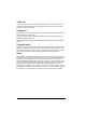
Getting Acquainted with Your Printer Space Requirements To ensure easy operation, consumable replacement and maintenance, adhere to the recommended space requirements detailed below. 913 mm (35.9") 469 mm (18.5") 244 mm (9.6") 100 mm (3.9") 244 mm (9.6") 100 mm (3.9") 385 mm (15.2") 436 mm (21.6") 51 mm (2.0") 100 mm (3.9") Front View 913 mm (35.9") 469 mm (18.5") 385 mm (15.2") 112.5 mm (4.4") 548.5 mm (21.6") 51 mm (2.0") 100 mm (3.
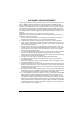
962 mm (37.9") 326 mm (12.8") 536 mm (21.1") 100 mm (3.9") Side View with Options " The option appears shaded in the above illustrations.
Printer Parts The following drawings illustrate the parts of your printer referred to throughout this guide, so please take some time to become familiar with them.
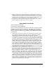
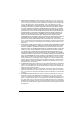
Rear View 8 7 1—KONICA MINOLTA Digital Camera Direct Print Port 1 2—Power switch 3—Power connection 4—Parallel port 5—10Base-T/100Base-TX/ 1000Base-T Ethernet Interface port 6 2 5 6—USB port 4 3 7—Ventilation grilles 8—Paper stopper Front View with Options 1—Lower feeder unit (Tray 3) 1 Getting Acquainted with Your Printer 5
6 Getting Acquainted with Your Printer
About the Software
Printer Driver CD-ROM PostScript Drivers Operating System Windows Vista/XP/Server 2003/ 2000 Windows Vista/XP/Server 2003 for 64bit " Use/Benefit These drivers give you access to all of the printer features, including finishing and advanced layout. See also “Displaying Printer Driver Settings (for Windows)” on page 15. A specific PPD file has been prepared for applications (such as PageMaker and Corel Draw) that require that a PPD file be specified when printing.
PPD Files Operating System Use/Benefit Macintosh OS X These files are required in order to use the printer driver for each operating system. For details of the Macintosh and Linux printer drivers, refer to the Reference Guide on the Utilities and Documentation CD-ROM. Linux " For details on the installation of the Windows printer drivers, refer to the Installation Guide on the Utilities and Documentation CD-ROM.
10 Utility Use/Benefit PageScope Web Connection With a Web browser, the status of printers can be checked, and the various settings can be changed. For details, refer to the Reference Guide on the Utilities and Documentation CD-ROM. PageScope Network Setup Using the TCP/IP and IPX protocols, basic network printer settings can be specified. For details, refer to the PageScope Network Setup User Manual on the Utilities and Documentation CD-ROM.
System Requirements Personal computer – Pentium 2: 400 MHz (Pentium 3: 500 MHz or higher is recommended) – Power Mac G3 or later (G4 or later is recommended) – Macintosh equipped with an Intel processor Operating System – Microsoft Windows Vista Home Basic/Home Premium/Ultimate/Business/Enterprise, Windows Vista Home Basic /Home Premium /Ultimate/Business /Enterprise x64 Edition, Windows XP Home Edition/Professional (Service Pack 1 or later; Service Pack 2 or later is recommended), Windows XP Professi
Selecting Driver Options/Defaults (for Windows) Before you start working with your printer, you are advised to verify/change the default driver settings. Also, in case you have options installed, you should “declare” the options in the driver.
" " 7 10 11 12 13 If Memory Card is selected, select Disable, Enable (1 GB Under), or Enable (1 GB Over), according to the installed CompactFlash card. Click Apply. " 8 9 If Printer Memory is selected, select 256 MB, 512 MB or 768 MB according to the installed memory. The factory default setting is 256 MB. Depending on the version of the operating system, Apply may not appear. If this is the case, continue with the next step. Select the General tab. Click Printing Preferences.
Uninstalling the Printer Driver (for Windows) This section describes how to uninstall the KONICA MINOLTA mc4650 printer driver if necessary. Windows Vista/XP/Server 2003/2000(KONICA MINOLTA mc4650 PCL6, KONICA MINOLTA mc4650PS) 1 2 Close all applications. Choose the Uninstall Program as follows: – (Windows Vista/XP/Server 2003) From the Start menu, choose All programs, KONICA MINOLTA, magicolor 4650, and then Uninstall Printer Driver.
Displaying Printer Driver Settings (for Windows) Windows Vista 1 2 From the Start menu, click Control Panel, then Hardware and Sound, and then click Printers to open the Printers directory. Right-click the KONICA MINOLTA mc4650 PCL6, or KONICA MINOLTA mc4650 PS printer icon, and then click Printing Preferences. Windows XP/Server 2003 1 2 From the Start menu, choose Printers and Faxes to display the Printers and Faxes directory.
Using the Postscript and PCL Printer Driver Common Buttons The buttons described below appear on each tab. OK Click to exit the Properties dialog box, saving any changes made. Cancel Click to exit the Properties dialog box without saving any changes made. Apply Click to save all changes without exiting the Properties dialog box. Help Click to view the help. Favorite Setting This allows the current settings to be saved. To save the current settings, specify the desired settings, and then click Add.
" This button does not appear on the Quality tab. Printer View Click the button to display an image of the printer (with all installed options) in the figure area. Quality View Click this button to display a sample of the settings selected in the Quality tab. " This button appears only when the Quality tab is selected. Default Click this button to reset the settings to their defaults.
Save a confidential job on the printer and protect it with a password Print a single copy for proofing Specify user authentication and account track settings Print on the back side of paper that has already been printed on " " Use paper that has been printed on with this printer. In addition, the page printed with this setting is not guaranteed. Do not use the following types of paper.
The settings in the “Overlay” function of the Watermark/Overlay tab allows you to Select the form to use Add or delete overlay files Launch Download Manager to download a form (PostScript printer driver only) " Download Manager Application should be installed earlier.
Print using the printer’s fonts Control the tones of an image (Contrast) (PCL printer driver only) Specify the image compression method (PCL printer driver only) Other Tab The Other Tab allows you to Select that Microsoft Excel sheets are not to be divided when printing Select that the white background of Microsoft PowerPoint data does not hide overlay files (PCL printer driver only) Send a notification by e-mail when printing is finished Shows the version information for the printer driver
Using the Status Monitor (Windows Only)
Working with the Status Monitor Introduction The Status Monitor shows information about the current status of the printer. The Status Monitor can be installed from the Utilities and Documentation CD-ROM. For details on the installation, refer to the Reference Guide on the Utilities and Documentation CD-ROM. Operating Environment The Status Monitor can be used on computers running Windows Vista/XP/ Server 2003/2000 connected to the printer using an Ethernet connection.
Printer Alerts—Displays text messages that alert you of conditions such as low toner. Recovery Instructions—Provides you with explanations of what you need to do in order to correct problems and recover from error conditions. Consumables Tab Displays the usage status (approximate percentage remaining) of each consumables. Order Supplies—Click Order Supplies to automatically access the order page for supplies.
24 Closing the Status Monitor
Printer Control Panel and Configuration Menu
About the Control Panel The control panel, located on the top of the printer, allows you to direct the printer’s operation. In addition, it displays the current status of the printer, including any condition that needs your attention.
Control Panel Indicators and Keys No. Key 1 Function Cancels the currently displayed menu or menu choice Allows you to cancel one or all print jobs that are currently being printed or processed: 1. Press the Cancel key. 2. Press the or keys to select either CUR- RENT JOB or ALL JOBS. 3. Press the Menu/Select key. The print job(s) is (are) cancelled.
No. Key Function 6 Moves the cursor to the left Displays the previous help screen appears in the message window Message Window The current status of the printer, the amount of toner remaining, and any error messages can be viewed from the message window. 1 2 3 5 4 No. Details 1 The printer status is indicated by the color of the indicator and lighting/flashing of the message window.
No. Details 2 The current status of the printer is displayed. If the operator or service representative must be called, the symbol and the error status are displayed. If a warning occurs, the symbol appears. When a digital camera is connected to the KONICA MINOLTA Digital Camera Direct Print Port with a USB cable, the symbol appears on the right side of the message window.
Configuration Menu Overview The configuration menu accessible from the control panel is structured as shown below. Main Menu READY PROOF/ PRINT MENU* PRINT MENU PAPER MENU QUALITY MENU MEMORY DIRECT** CAMERA DIRECT*** INTERFACE MENU SYS DEFAULT MENU MAINTENANCE MENU SERVICE MENU " 30 * This menu item appears only if an optional hard disk kit is installed. ** This menu item appears when an optional hard disk kit or a CompactFlash card is installed, and INTERFACE MENU/MEMORY DIRECT is set to ENABLE.
" MEMORY DIRECT and CAMERA DIRECT do not appear if public user access has not been permitted through authentication settings. For details on the authentication settings, refer to the Reference Guide on the Utilities and Documentation CD-ROM.
PROOF/PRINT MENU " This menu item appears only if an optional hard disk kit is installed. With this menu item, print jobs that were set to be saved on the hard disk by using Job Retention on the Basic tab of the printer driver can be printed or deleted. " All factory default values are shown in bold. PROOF/ PRINT MENU “User name” “Job name” PRINT DELETE “Job name” COPIES 1 “Job name” YES NO Printing/Deleting a Stored Job 1 Follow the procedure described below to select a job.
Press Key Until Display Reads Desired user name , Press until the desired user name appears. “Job name” Desired job name , Press until the desired job name appears. PRINT DELETE If the selected print job was set as a secured job from the printer driver, a screen for entering the password appears. For details on typing the password, refer to “Entering the Password” on page 34. 2 Select PRINT or DELETE, and then press the Menu/Select key. " 3 4 5 6 If PRINT was selected, continue with step 3.
Entering the Password If the print job selected in the PROOF/PRINT MENU is a secured job, a screen for entering the password appears. Follow the procedure described below to type in the four-digit password specified from the printer driver. 1 2 3 4 5 Press the word. to increase or the to decrease the first digit of the pass- Press the key to move the cursor to the next digit. Press the password.
PRINT MENU With this menu, printer information, such as the configuration page and the demo page, can be printed. PRINT MENU CONFIGURATION PG DEMO PAGE STATISTICS PAGE FONT LIST POSTSCRIPT PCL MENU MAP DIRECTORY LIST* " " * This menu item appears only if an optional hard disk kit or a CompactFlash card is installed. All factory default values are shown in bold. CONFIGURATION PG Settings DEMO PAGE Settings PRINT/CANCEL Prints the configuration page. PRINT/CANCEL Prints the demo page.
FONT LIST POST SCRIPT Settings PCL Settings PRINT/CANCEL Prints the PostScript font list. PRINT/CANCEL Prints the PCL font list. MENU MAP Settings PRINT/CANCEL Prints the menu map. DIRECTORY LIST 36 Settings PRINT/CANCEL Prints the directory list of the hard disk or a CompactFlash card .
PAPER MENU With this menu, the paper used for printing can be managed.
" " * This menu item appears only when you select CUSTOM from the TRAY 1/PAPER SIZE menu. **This menu item appears only when you select CUSTOM from the TRAY 2/PAPER SIZE menu. *** This menu item appear only if the optional lower feeder unit is installed. **** This menu item appears only magicolor 4650DN. ***** This menu item appears only if an optional hard disk kit or a CompactFlash card of 1 GB or more is installed. All factory default values are shown in bold.
CUSTOM Specify the paper size when custom-sized paper is loaded into Tray 1. SIZE The setting units can be switched between millimeters and inches with the SYS DEFAULT MENU/PAPER/UNIT OF MEASURE setting. Setting range for WIDTH For MILLIMETERS: 92 to 216 mm (default) – North America: 216 mm – All other regions: 210 mm For INCHES: 3.63 to 8.50 inches (default) – North America: 8.50 inches – All other regions: 8.
PAPER TYPE Settings ANY/PLAIN PAPER/ RECYCLED/THICK 1/ THICK 2/LABEL/ TRANSPARENCY/ ENVELOPE/POSTCARD/ LETTERHEAD/GLOSSY 1/ GLOSSY 2 Select the setting for the type of paper loaded into Tray 1. TRAY 2 PAPER SIZE Settings ANY/LETTER/EXECUTIVE/ A4/A5/A6/ B5(JIS)/B6(JIS)/GOVT LETTER/STATEMENT/UK QUARTO/16K/PHOTO 4×6/ KAI 16/KAI 32/CUSTOM Select the setting for the size of paper loaded into Tray 2. " The default setting for North America is LETTER. The default setting for all other regions is A4.
CUSTOM Specify the paper size when custom-sized paper is loaded into Tray 2. SIZE The setting units can be switched between millimeters and inches with the SYS DEFAULT MENU/PAPER/UNIT OF MEASURE setting. Setting range for WIDTH For MILLIMETERS: 92 to 216 mm (default) – North America: 216 mm – All other regions: 210 mm For INCHES: 3.63 to 8.50 inches (default) – North America: 8.50 inches – All other regions: 8.
TRAY 3 PAPER SIZE The size of paper loaded in Tray 3 is indicated. This menu item only shows the current setting. This setting cannot be changed. PAPER TYPE Settings ANY/PLAIN PAPER/ RECYCLED Select the setting for the type of paper loaded into Tray 3. Settings ON/OFF TRAY CHAINING If ON is selected and the specified tray runs out of paper during printing, a tray loaded with paper of the same size is automatically selected so printing can continue.
DUPLEX Settings OFF/LONG EDGE/SHORT EDGE If LONG EDGE is selected, the pages will be printed on both sides of the paper for long-edge binding. If SHORT EDGE is selected, the pages will be printed on both sides of the paper for short-edge binding. The setting specified in the printer driver will override this menu setting. " For magicolor 4650DN only COPIES Settings 1-9999 Specify the number of copies to be printed. The setting specified in the printer driver will override this menu setting.
QUALITY MENU With this menu, settings for the print quality can be specified.
TEXT PRINTING RGB SOURCE RGB INTENT RGB GRAY GRAPHICS PRINTING RGB SOURCE RGB INTENT RGB GRAY PS SETTING IMAGE PRINTING RGB SOURCE RGB INTENT RGB GRAY DESTINATION PROF TEXT PRINTING RGB SOURCE RGB INTENT RGB GRAY DESTINATION PROF GRAPHICS PRINTING RGB SOURCE RGB INTENT RGB GRAY DESTINATION PROF Configuration Menu Overview 45
CALIBRATION SIMULATION SIMULATION PROF TONE CALIBRATION SIMULATION INTENT AIDC PROCESS CMYK GRAY CMYK DENSITY CYAN COLOR SEPARATION MAGENTA YELLOW BLACK " All factory default values are shown in bold. COLOR MODE Settings COLOR/GRAYSCALE If COLOR is selected, the pages are printed in full color. If GRAYSCALE is selected, the pages are printed in black and white. BRIGHTNESS Settings -15%/-10%/-5%/0%/+5%/+10%/ +15% The brightness of the printed image can be adjusted.
TEXT PRINTING Settings LINE ART/DETAIL/ SMOOTH Select how halftones in text are reproduced. If LINE ART is selected, halftones are reproduced with high precision. If DETAIL is selected, halftones are reproduced with detail. If SMOOTH is selected, halftones are reproduced with smoothness. GRAPHICS PRINTING Settings LINE ART/DETAIL/ SMOOTH Select how halftones in graphics are reproduced. If LINE ART is selected, halftones are reproduced with high precision.
TEXT PRINTING Settings ON/OFF Select whether text edges are emphasized. If ON is selected, the edges are emphasized. If OFF is selected, the edges are not emphasized. GRAPHICS PRINTING Settings ON/OFF Select whether graphic edges are emphasized. If ON is selected, the edges are emphasized. If OFF is selected, the edges are not emphasized. " If ECONOMY PRINT is set to ON, the edges cannot be emphasized.
ECONOMY PRINT Settings ON/OFF Select whether to print graphics with a reduced density by reducing the amount of toner that is used. If ON is selected, the amount of toner used is reduced when printing. If OFF is selected, the amount of toner used is not reduced when printing. " If ON is selected, the edges are not emphasized, even if IMAGE PRINTING and GRAPHICS PRINTING of the EDGE ENHANCEMENT menu item are set to ON.
RGB GRAY Settings COMPOSITE BLACK/BLACK AND GRAY/ BLACK ONLY Specify how black and grays are reproduced in RGB image data. If COMPOSITE BLACK is selected, black is reproduced using the CMYK colors. If BLACK AND GRAY is selected, black and gray are reproduced using black only. If BLACK ONLY is selected, black is reproduced using only black. TEXT PRINTING Settings RGB SOURCE DEVICE COLOR/ sRGB Specify the color space for RGB text data. If DEVICE COLOR is selected, no color space is specified.
Settings RGB INTENT VIVID/ PHOTOGRAPHIC Specify the characteristic applied when converting RGB text data to CMYK data. If VIVID is selected, a vivid output is produced. If PHOTOGRAPHIC is selected, a brighter output is produced. RGB GRAY Settings COMPOSITE BLACK/BLACK AND GRAY/ BLACK ONLY Specify how black and grays are reproduced in RGB text data. If COMPOSITE BLACK is selected, black is reproduced using the CMYK colors. If BLACK AND GRAY is selected, black and gray are reproduced using black only.
Settings RGB INTENT VIVID/ PHOTOGRAPHIC Specify the characteristic applied when converting RGB GRAPHICS data to CMYK data. If VIVID is selected, a vivid output is produced. If PHOTOGRAPHIC is selected, a brighter output is produced. RGB GRAY Settings COMPOSITE BLACK/BLACK AND GRAY/ BLACK ONLY Specify how black and grays are reproduced in RGB GRAPHICS data. If COMPOSITE BLACK is selected, black is reproduced using the CMYK colors.
PS SETTINGS IMAGE PRINTING Settings RGB SOURCE DEVICE COLOR/ sRGB/ AppleRGB/ AdobeRGB1998/ ColorMatchRGB/ BlueAdjustRGB Specify the color space for RGB image data. If DEVICE COLOR is selected, no color space is specified. If RGB source profiles are downloaded with the Download Manager, they are available from the list of settings. Settings RGB INTENT VIVID/ PHOTOGRAPHIC/ RELATIVE COLOR/ ABSOLUTE COLOR Specify the characteristic applied when converting RGB image data to CMYK data.
RGB GRAY Settings COMPOSITE BLACK/BLACK AND GRAY/ BLACK ONLY Specify how black and grays are reproduced in RGB image data. If COMPOSITE BLACK is selected, black is reproduced using the CMYK colors. If BLACK AND GRAY is selected, black and gray are reproduced using black only. If BLACK ONLY is selected, black is reproduced using only black. DESTI- Settings AUTO NATION Specify the destination profile.
TEXT PRINTING Settings RGB SOURCE DEVICE COLOR/ sRGB/ AppleRGB/ AdobeRGB1998/ ColorMatchRGB/ BlueAdjustRGB Specify the color space for RGB text data. If DEVICE COLOR is selected, no color space is specified. If RGB source profiles are downloaded with the Download Manager, they are available from the list of settings. Settings RGB INTENT VIVID/ PHOTOGRAPHIC/ RELATIVE COLOR/ ABSOLUTE COLOR Specify the characteristic applied when converting RGB text data to CMYK data.
RGB GRAY Settings COMPOSITE BLACK/BLACK AND GRAY/ BLACK ONLY Specify how black and grays are reproduced in RGB text data. If COMPOSITE BLACK is selected, black is reproduced using the CMYK colors. If BLACK AND GRAY is selected, black and gray are reproduced using black only. If BLACK ONLY is selected, black is reproduced using only black. DESTI- Settings AUTO NATION Specify the destination profile.
GRAPHICS PRINTING Settings RGB SOURCE DEVICE COLOR/ sRGB/ AppleRGB/ AdobeRGB1998/ ColorMatchRGB/ BlueAdjustRGB Specify the color space for RGB image data. If DEVICE COLOR is selected, no color space is specified. If RGB source profiles are downloaded with the Download Manager, they are available from the list of settings. Settings RGB INTENT VIVID/ PHOTOGRAPHIC/ RELATIVE COLOR/ ABSOLUTE COLOR Specify the characteristic applied when converting RGB image data to CMYK data.
RGB GRAY Settings COMPOSITE BLACK/BLACK AND GRAY/ BLACK ONLY Specify how black and grays are reproduced in RGB image data. If COMPOSITE BLACK is selected, black is reproduced using the CMYK colors. If BLACK AND GRAY is selected, black and gray are reproduced using black only. If BLACK ONLY is selected, black is reproduced using only black. DESTI- Settings AUTO NATION Specify the destination profile.
SIMULATION SIMU- Settings LATION PROF NONE/SWOP/ Euroscale/ CommercialPre ss/TOYO/DIC Specify the simulation profile. If NONE is selected, no simulation profile is specified. If simulation profiles are downloaded with the Download Manager, they are available from the list of settings. SIMU- Settings LATION INTENT RELATIVE COLOR/ ABSOLUTE COLOR Specify the characteristic of the simulation profile. If RELATIVE COLOR is selected, relative color is applied to the simulation profile.
CMYK GRAY Settings COMPOSITE BLACK/BLACK AND GRAY/ BLACK ONLY Specify how black and grays are reproduced using the four CMYK colors. If COMPOSITE BLACK is selected, black is reproduced using the CMYK colors. If BLACK AND GRAY is selected, black and gray are reproduced using black only. If BLACK ONLY is selected, black is reproduced using only black. CALIBRATION Settings ON/OFF TONE CALIBRATION If ON is selected, image adjustments are applied. If OFF is selected, image adjustments are not applied.
CMYK DENSITY CYAN/ HIGHMAGENTA/ LIGHT YELLOW/ BLACK Settings -3/-2/ -1/0/ +1/+2/ +3 The density of the highlight color in images can be adjusted. MIDDLE Settings -3/-2/ -1/0/ +1/+2/ +3 The density of the middle color in images can be adjusted. SHADOW Settings -3/-2/ -1/0/ +1/+2/ +3 The density of the shadow color in images can be adjusted. COLOR SEPARATION Settings ON/OFF If ON is selected, color separation are performed.
MEMORY DIRECT This menu item appears when an optional hard disk kit or a CompactFlash card is installed, and INTERFACE MENU/MEMORY DIRECT is set to ENABLE. In addition, this menu item does not appear if public user access has not been permitted through authentication settings. For details on the authentication settings, refer to the Reference Guide on the Utilities and Documentation CD-ROM. With this menu, settings for “memory direct” function can be specified.
Letter/ Settings A4 LETTER/LEGAL/EXECUTIVE/A4/ A5/A6/B5(JIS)/B6(JIS)/GOVT LETTER/STATEMENT/FOLIO/SP FOLIO/UK QUARTO/FOOLSCAP/ GOVT LEGAL/16K/PHOTO 4×6/ KAI 16/KAI 32/ENV C6/ENV DL/ENV MONARCH/ENV CHOU#3/ ENV CHOU#4/B5(ISO)/ENV #10/ JPOST/JPOST-D/CUSTOM Change the size of the paper. " The default setting for North America is LETTER. The default setting for all other regions is A4. " Depending on the setting selected for SYS DEFAULT MENU/PAPER/UNIT OF MEASURE, PHOTO 4×6 may change to PHOTO 10×15.
COLLATE Settings ON/OFF Select whether to collate the copies. If ON is selected, collated printing is performed. If OFF is selected, collated printing is not performed. " This menu item appears only if the optional hard disk kit or a CompactFlash card of 1GB or more is installed. TYPE OF FILES 64 Settings PDF,XPS,JPEG,TIFF/PDF,XPS Select the type of files to be displayed.
CAMERA DIRECT This menu item appears when INTERFACE MENU/CAMERA DIRECT is set to ENABLE. In addition, this menu item does not appear if public user access has not been permitted through authentication settings. For details on the authentication settings, refer to the Reference Guide on the Utilities and Documentation CD-ROM. With this menu, settings for “camera direct” function can be specified. " These settings are overridden by any settings configured within the digital camera.
" All factory default values are shown in bold. PAPER Settings TRAY1/TRAY2/TRAY3 SOURCE Select the tray that is used for camera direct printing. " TRAY3 appears only if the optional lower feeder unit is installed. LAYOUT Settings 1-UP/2-UP/3-UP/4-UP/6-UP/8-UP Specify the number of images printed on a single sheet of media. When set to 1-UP, only one image will be printed on a single sheet of media.
RGB SOURCE Settings DEVICE COLOR/sRGB Specify the color space for RGB image data. If DEVICE COLOR is selected, no color space is specified. RGB INTENT Settings VIVID/PHOTOGRAPHIC Specify the characteristic applied when converting RGB image data to CMYK data. If VIVID is selected, a vivid output is produced. If PHOTOGRAPHIC is selected, a brighter output is produced. RGB GRAY Settings COMPOSITE BLACK/BLACK AND GRAY/BLACK ONLY Specify how black and grays are reproduced in RGB image data.
INTERFACE MENU With this menu, interface settings can be specified. " Restart the printer after changing settings in the ETHERNET menu.
" ENABLE RAW PORT* BIDIRECTIONAL SLP* ENABLE SMTP* ENABLE SNMP* ENABLE WSD PRINT* ENABLE IPSEC* ENABLE IP ADDRESS FILTER* ACCESS PERMISSION ACCESS REFUSE IPv6* ENABLE NETWARE ENABLE AUTO SETTING APPLETALK ENABLE LINK LOKAL GLOBAL ADDRESS SPEED/ DUPLEX IEEE802.1X " GATEWAY ADDRESS ENABLE *This menu item appears when INTERFACE MENU/ETHERNET/ TCP/IP/ENABLE is set to YES. ** This menu item appears only if an optional hard disk kit or a CompactFlash card is installed.
" All factory default values are shown in bold. JOB TIMEOUT Settings 5 seconds-15 seconds-300 seconds Specify the timeout interval for a print job being received. ETHER- TCP/IP NET ENABLE Settings YES/NO If YES is selected, TCP/IP is enabled. If NO is selected, TCP/IP is disabled. Setting IP 000.000.000.000 ADDRESS Set the IP address for this printer on the network. Use the , , specify the value. , and keys to If the IP address is manually specified, DHCP/BOOTP is automatically set to OFF.
BOOTP Settings ON/OFF Select whether or not the IP address is automatically acquired. If ON is selected, the IP address is automatically acquired. If OFF is selected, the IP address is not automatically acquired. ARP/ PING Settings ON/OFF Select whether or not the IP address is automatically acquired. If ON is selected, the IP address is automatically acquired. If OFF is selected, the IP address is not automatically acquired. HTTP ENABLE Settings YES/NO If YES is selected, HTTP is enabled.
DYNAMIC ENABLE Settings YES/NO DNS If YES is selected, Dynamic DNS is enabled. If NO is selected, Dynamic DNS is disabled. IPP ENABLE Settings YES/NO If YES is selected, IPP is enabled. If NO is selected, IPP is disabled. RAW PORT ENABLE Settings YES/NO If YES is selected, Raw Port is enabled. If NO is selected, Raw Port is disabled. BIDI- Settings ON/OFF RECIf ON is selected, Raw port TIONAL transmissions are enabled. If OFF is selected, Raw port transmissions are disabled.
WSD PRINT ENABLE Settings YES/NO If YES is selected, WSD print is enabled. If NO is selected, WSD print is disabled. IPSEC ENABLE Settings YES/NO If YES is selected, IPsec is enabled. If NO is selected, IPsec is disabled. IP ACCESS Settings ENABLE/ ADDRESS PERDISABLED FILTER MISSelect whether to enable or SION disable access granting. If ENABLE is selected, access granting is enabled. If DISABLE is selected, access granting is disabled.
AUTO SETTING Settings YES/NO If YES is selected, auto configuration of IPv6 is enabled. If NO is selected, auto configuration of IPv6 is disabled. LINK LOKAL Displays the Link-Local address. GLOBAL Displays the global address. ADDRESS GATE- Displays the gateway address. WAY ADDRESS NETWARE ENABLE Settings YES/NO If YES is selected, NetWare is enabled. If NO is selected, NetWare is disabled. APPLE TALK ENABLE Settings YES/NO If YES is selected, AppleTalk is enabled.
CAMERA Settings ENABLE/DISABLE DIRECT Select whether to enable or disable camera direct printing. If ENABLE is selected, camera direct printing is enabled. If DISABLE is selected, camera direct printing is disabled.
SYS DEFAULT MENU With this menu, settings can be specified to adjust the operation of the printer, such as the display language of the message window and the time until the machine enters Energy Saver mode. SYS DEFAULT MENU LANGUAGE EMULATION DEF.
HOLD JOB TIMEOUT* ENERGY SAVER ENERGY SAVER TIME** MENU TIMEOUT LCD CONTRAST SECURITY CHANGE PASSWORD LOCK PANEL CLOCK DATE (xx.xx.
ENABLE WARNING " 78 PAPER EMPTY TRAY1 TONER LOW TRAY2 I-UNIT LOW TRAY3**** * These menu items appear only if an optional hard disk kit is installed. ** This menu item appears when you select ON from the ENERGY SAVER menu. *** This menu item appears only if an optional CompactFlash card is installed. **** This menu item appears only if the optional lower feeder unit is installed. ***** This menu item appears only if an optional hard disk kit or a CompactFlash card is installed.
" All factory default values are shown in bold. LANGUAGE Settings ENGLISH/FRENCH/GERMAN/SPANISH/ ITALIAN/PORTUGUESE/CZECH/JAPANESE/ KOREAN/SIMPLIFIED CHINESE/ TRADITIONAL CHINESE/DUTCH/RUSSIAN/ POLISH The display language of the message window can be changed to the selected language. The language selections appear in the message window in the corresponding language. For example, GERMAN appears as DEUTSCH. Settings AUTO/POSTSCRIPT/PCL EMULA- DEF. TION EMULA- Specify the printer emulation language.
PCL CR/LF MAPPING Settings CR=CR LF=LF/CR=CRLF LF=LF/CR=CR LF=LFCR/CR=CRLF LF=LFCR Select the definitions of the CR/LF codes in the PCL language. LINES PER PAGE Settings 5-60-128 Specify the number of lines per page in the PCL language. Settings 0-102 FONT FONT SOURCE NUMBER Specify the default font in the PCL language. The font numbers that appear correspond to the PCL font list. For details on printing the font list, refer to “PRINT MENU” on page 35. PITCH Settings SIZE (POINT SIZE) 0.44-10.
XPS DIGTAL Settings ENABLE/DISABLE SIGNA- Select whether to enable or disable XPS TURE digital signatures. If ENABLE is selected, XPS digital signatures are enabled. If DISABLE is selected, XPS digital signatures are disabled. XPS ERROR PAGE Settings ON/OFF Select whether or not an error report is printed after an XPS error has occurred. If ON is selected, the error report is printed. If OFF is selected, the error report is not printed.
CUSTOM Specify the media size when PAPER SIZE SIZE is set to CUSTOM. The setting units can be switched between millimeters and inches with the SYS DEFAULT MENU/PAPER/UNIT OF MEASURE setting. Setting range for WIDTH For MILLIMETERS: 92 to 216 mm (default) – North America: 216 mm – All other regions: 210 mm For INCHES: 3.63 to 8.50 inches (default) – North America: 8.50 inches – All other regions: 8.
PAPER TYPE Settings PLAIN PAPER/ RECYCLED/THICK 1/ THICK 2/LABEL/ TRANSPARENCY/ ENVELOPE/POSTCARD/ LETTERHEAD/GLOSSY 1/ GLOSSY 2 Select the type of media that is normally used. UNIT OF MEASURE Settings INCHES/MILLIMETERS The units for specifying the size of custom media can be switched between inches and millimeters. " The default setting for North America is INCHES. The default setting for all other regions is MILLIMETERS.
AUTO CONTINUE Settings ON/OFF Select whether or not printing continues if the size or type of media in the selected tray is different from the size or type of media for the print job. If AUTO CONTINUE is set to ON, printing automatically continues after about 10 seconds under the following conditions. At this time, printing will be performed even if the media size is different.
LCD CONTRAST Settings SECURITY CHANGE Specify the password for locking the control panel. PASSIf the password is set to 0000 (default), the control WORD panel is not locked. In order to lock the control panel, be sure to specify a password other than 0000. -3/-2/-1/0/+1/+2/+3 Adjust the contrast of the message window. The darkest level setting is -3 and the brightest level setting is +3. LOCK PANEL Settings OFF/MINIMUM/ON Specify how the control panel is locked.
CARD USER FORMAT AREA ONLY ALL Initialize the user area of the compactflash card. When this menu item is selected, the printer is automatically restarted. Initialize the compactflash card. When this menu item is selected, the printer is automatically restarted. RESTORE RESTORE Reset the network settings to their defaults. When DEFAULTS NETWORK this menu item is selected, the printer is automatically restarted. RESTORE Reset the printer settings to their defaults.
MAINTENANCE MENU With this menu, maintenance on this printer can be performed. In order to use this menu, the administrator password must be entered.
ENVELOPE LABEL GLOSSY 1 GLOSSY 2 IMG ADJ THICK DUPLEX PASS* PLAIN PAPER MANUAL DUPLEX PLAIN PAPER CYAN THICK 1 MAGENTA THICK 2 YELLOW POSTCARD BLACK ENVELOPE LABEL IMG ADJ BLACK GLOSSY 1 GLOSSY 2 SUPPLIES REPLACE TRANS. BELT TRANS.
" " " * This menu item appears only magicolor 4650DN. **This menu item appears when a USB memory device is plugged into the KONICA MINOLTA Digital Camera Direct Port. All factory default values are shown in bold. PRINT MENU EVENT LOG Settings HALFTONE 64 CYAN/ Settings PRINT/CANCEL MAGENTA/ Print cyan/magenta/yellow/black halfYELLOW/ tones at 64 gradations. BLACK 64 HALFTONE 128 CYAN/ Settings PRINT/CANCEL MAGENTA/ Print cyan/magenta/yellow/black halfYELLOW/ tones at 128 gradations.
LEFT LEFT ADJUST ADJ MENT TRAY1 Settings LEFT ADJ TRAY2 Settings LEFT ADJ TRAY3 Settings LEFT LEFT ADJ ADJ DUPLEX TRAY1 Settings LEFT ADJ TRAY2 Settings LEFT ADJ TRAY3 Settings TRANS- SIMFER PLEX POWER PASS -15-15 When printing on media in Tray 1, specify the size of the left margin. -15-15 When printing on media in Tray 2, specify the size of the left margin. -15-15 When printing on media in Tray 3, specify the size of the left margin.
THICK 1 Settings THICK 2 Settings POSTCARD Settings -8-7 When printing on thick 1 using simplex pass, correct the secondary image transfer current. -8-7 When printing on thick 2 using simplex pass, correct the secondary image transfer current. -8-7 When printing on postcard using simplex pass, correct the secondary image transfer current. ENVELO Settings -8-7 PE When printing on envelope using simplex pass, correct the secondary image transfer current.
MANUAL PLAIN DUPLEX PAPER Settings THICK 1 Settings THICK 2 Settings POSTCARD Settings ENVELOPE Settings LABEL Settings -8-7 When printing on plain paper using manual duplex pass, correct the secondary image transfer current. -8-7 When printing on THICK 1 using manual duplex pass, correct the secondary image transfer current. -8-7 When printing on THICK 2 using manual duplex pass, correct the secondary image transfer current.
GLOSSY Settings -8-7 2 When printing on GLOSSY 2 using manual duplex pass, correct the secondary image transfer current. IMG ADJ THICK CYAN Settings -5-0-5 When printing on thick paper, adjust the cyan in the image. MAGENTA Settings -5-0-5 When printing on thick paper, adjust the magenta in the image. YELLOW Settings -5-0-5 When printing on thick paper, adjust the yellow in the image. BLACK Settings -5-0-5 When printing on thick paper, adjust the black in the image.
QUICK SETTING UPDATE SETTING Setup EXECUTE / CANCEL Select whether or not to update the printer settings from the definitions file on the USB memory device. If EXECUTE is selected, the printer settings are updated. If CANCEL is selected, the settings are not updated. BACKUP SETTING Backup EXECUTE / CANCEL Select whether or not to save the printer settings information on a USB memory device. If EXECUTE is selected, the printer settings are saved on a USB memory device.
Camera Direct
Camera Direct If a digital camera with PictBridge (1.0 or later) is connected to the printer through the Camera Direct Print port, images stored on the digital camera can be printed directly from the printer. " " For details on using the digital camera, refer to your digital cameras manual. The following features are not supported with Camera Direct.
Memory Direct
Memory Direct PDF, XPS, JPEG and TIFF files saved on USB memory devices can be printed by plugging the USB memory device into the printer. " " Memory direct can be used only if the optional hard disk kit or a CompactFlash card is installed. In order to perform collated printing with memory direct, the optional hard disk kit or a CompactFlash card of 1 GB or more must be installed. For details on specifying settings with the control panel, refer to “MEMORY DIRECT” on page 62.
Using Media
Media Specifications What types and sizes of media can I load? Media Media Size Inch Tray* Millimeter Duplex** (double-sided) Letter 8.5 x 11.0 215.9 x 279.4 1/2/3 Yes Legal 8.5 x 14.0 215.9 x 355.6 1/3 Yes Statement 5.5 x 8.5 139.7 x 215.9 1/2 No Executive 7.25 x 10.5 184.2 x 266.7 1/2/3 Yes A4 8.2 x 11.7 210.0 x 297.0 1/2/3 Yes A5 5.9 x 8.3 148.0 x 210.0 1/2 No A6 4.1 x 5.8 105.0 x 148.0 1/2 No B5 (JIS) 7.2 x 10.1 182.0 x 257.0 1/2/3 Yes B6 5.0 x 7.2 128.
" For custom sizes, use the printer driver to specify the settings within the ranges shown in the table on previous page. Media Types Before purchasing a large quantity of special media, do a trial print with the same media and check the print quality. Keep media on a flat, level surface in its original wrapper until it is time to load it. For a list of approved media, refer to printer.konicaminolta.com.
DO NOT use media that is Coated with a processed surface (such as carbon paper, and colored paper that has been treated) Carbon backed Unapproved iron-on transfer media (such as heat-sensitive paper, heat-pressure paper, and heat-press transfer paper) Cold-water-transfer paper Pressure sensitive Designed specifically for inkjet printers (such as superfine paper, glossy paper, glossy film, and postcards) Paper that has already been printed on – Paper that has been printed on with an inkjet
Thick Stock Paper thicker than 90 g/m2 (24 lb bond) is referred to as thick stock. Test all thick stock to ensure acceptable performance and to ensure that the image does not shift. Capacity Tray 1 Up to 20 thick stock sheets, depending on (Manual Feed their thickness. Tray) Tray 2/3 Not supported Orientation Face down Driver Thick 1 (91-150 g/m2) Media Type Thick 2 (151-210 g/m2) Weight 91–210 g/m² (25–55.
Dry DO NOT use envelopes that have Sticky flaps Tape seals, metal clasps, paper clips, fasteners, or peel-off strips for sealing Transparent windows Too rough of a surface Material that will melt, vaporize, offset, discolor, or emit dangerous fumes Been presealed Labels A sheet of labels consists of a face sheet (the printing surface), adhesive, and a carrier sheet: The face sheet must follow the plain paper specification.
" Labels may stick to the fuser, causing them to peel off and media misfeeds to occur. Are precut or perforated Do not use Shiny backed paper OK to use Full-page labels (uncut) Letterhead Try printing your data on a sheet of plain paper first to check placement.
Use postcards that are Approved for laser printers DO NOT use postcards that are Coated Designed for inkjet printers Precut or perforated Preprinted or multicolored " If the postcard is warped, press on the warped area before putting it in Tray 1. Transparencies " " " " Do not fan transparencies before loading them. Resulting static electricity may cause printing errors. If you touch the face of the transparencies with your bare hands, print quality may be affected.
" Always first test a small quantity of a particular type of transparency. Use transparencies that are Approved for laser printing DO NOT use transparencies that Have static electricity that will cause them to stick together Are specified for inkjet printers only Glossy Media Test all glossy media to ensure acceptable performance and to ensure that the image does not shift. Capacity Tray 1 Up to 20 glossy media sheets, depending on (Manual Feed their thickness.
What Is the Guaranteed Imageable (Printable) Area? The printable area on all media sizes is up to 4.2 mm (0.165") from the edges of the media. Each media size has a specific imageable area, the maximum area on which the printer can print clearly and without distortion. a a a Printable Area This area is subject to both hardware a limits (the physical media size and the margins required by the printer) and a = 4.2 mm (0.
Loading Media How do I load media? Take off the top and bottom sheets of a ream of paper. Holding a stack of approximately 100 sheets at a time, fan the stack to prevent static buildup before inserting it in a tray. " Do not fan transparencies. Note Although this printer was designed for printing on a wide range of media types, it is not intended to print exclusively on a single media type except plain paper.
2 3 4 110 Slide the media guides to provide more space between them. Press down on the center of the paper-lifting plate until the left and right locking tabs (white) lock into place. Load the paper face down in the tray.
" 5 6 Do not load so much paper that the top of the stack is higher than the maximum limit guide. Up to 100 sheets (80 g/m2 [22 lb]) of plain paper can be loaded into the tray at one time. Slide the media guides against the edges of the paper. Select PAPER MENU/PAPER SOURCE/TRAY 1/PAPER SIZE and PAPER TYPE in the configuration menu, and then select the setting for the size and type of paper that are loaded. See also “PAPER MENU” on page 37.
Loading Envelopes 1 2 3 112 Open Tray 1. Slide the media guides to provide more space between them. Press down on the center of the paper-lifting plate until the left and right locking tabs (white) lock into place.
4 Load the envelopes flap side up in the tray. " " " 5 Before loading envelopes, press them down to make sure that all air is removed, and make sure that the folds of the flaps are firmly pressed; otherwise the envelopes may become wrinkled or a media misfeed may occur. Up to 10 envelopes can be loaded into the tray at one time. For envelopes with the flap along the long edge (Envelope C6, Envelope Monarch, and Envelope DL), load the envelopes with the flap side up.
6 Select PAPER MENU/PAPER SOURCE/TRAY 1/PAPER SIZE and PAPER TYPE in the configuration menu, and then select the setting for the size and type of media that is loaded. See also “PAPER MENU” on page 37. Loading Label Sheets/Postcards/Thick Stock/Glossy Media and Transparencies 1 2 114 Open Tray 1. Slide the media guides to provide more space between them.
3 4 Press down on the center of the paper-lifting plate until the left and right locking tabs (white) lock into place. Load the media face down in the tray. " 5 6 Up to 20 sheets can be loaded into the tray at one time. Slide the media guides against the edges of the media. Select PAPER MENU/PAPER SOURCE/TRAY 1/PAPER SIZE and PAPER TYPE in the configuration menu, and then select the setting for the size and type of media that is loaded. See also “PAPER MENU” on page 37.
Tray 2 Loading Plain Paper 1 2 3 116 Pull out Tray 2. Press down the media pressure plate to lock it into place. Slide the media guides to provide more space between them.
4 Load the paper face up in the tray. " 5 Do not load above the mark. Up to 250 sheets (80 g/m2 [22 lb]) of plain paper can be loaded into the tray at one time. Slide the media guides against the edges of the paper.
6 7 118 Close Tray 2. Select PAPER MENU/PAPER SOURCE/TRAY 2/PAPER SIZE and PAPER TYPE in the configuration menu, and then select the setting for the size and type of paper that are loaded. See also “PAPER MENU” on page 37.
Tray 3 (Optional Lower Feeder Unit) Loading Plain Paper 1 2 3 Pull out Tray 3. Press down the media pressure plate to lock it into place. Slide the media guides to provide more space between them.
4 Load the paper face up in the tray. " 5 120 Do not load above the mark. Up to 500 sheets (80 g/m2 [22 lb]) of plain paper can be loaded into the tray at one time. Slide the media guides against the edges of the paper.
6 7 Close Tray 3. Select PAPER MENU/PAPER SOURCE/TRAY 3/PAPER TYPE in the configuration menu, and then select the setting for the type of paper that is loaded. See also “PAPER MENU” on page 37.
Duplexing Duplex (double-sided) printing can be done with magicolor 4650DN, which has the duplex unit built in as a standard. If the paper has low opacity (high translucency), then the printed data from one side of the page will show through to the other side. Check your application for margin information. For best results, print a small quantity to make sure the opacity is acceptable. Note Only plain paper, 60–90 g/m2 (16–24 lb bond) can be autoduplexed. See “Media Specifications” on page 100.
In addition, if “N-up” has been set to “Booklet”, autoduplex printing is performed. The following Order settings are available when “Booklet” is selected. If “Left Binding” is selected, the pages can be folded as a left-bound booklet. 2 1 1 If “Right Binding” is selected, the pages can be folded as a right-bound booklet. 1 2 3 3 3 1 2 3 1 Load plain paper into the tray. From the printer driver, specify duplex (double-sided) printing (Layout tab in Windows). Click OK.
Output Tray All printed media is output to the face-down output tray on top of the printer. This tray has a capacity of approximately 200 sheets (A4/Letter) of 80 g/m2 (22 lb) paper. " " " 124 If the media is stacked too high in the output tray, your printer may experience media misfeeds, excessive media curl, or static buildup.
Media Storage How do I store media? Keep media on a flat, level surface in its original wrapper until it is time to load it. Media that has been stored for a long time out of its packaging may dry up too much and cause misfeeding. If media has been removed from its wrapper, place it in its original packaging and store in a cool, dark place on a level surface. Avoid moisture, excessive humidity, direct sunlight, excessive heat (above 35°C [95°F]), and dust.
126 Media Storage
Replacing Consumables
Replacing Consumables Note Failure to follow instructions as outlined in this manual could result in voiding your warranty. Note If an error message (TONER OUT, TRANS.BELT END OF LIFE, etc.) appears, print out the configuration page, and then check the status of the other consumables. For details on the error messages, refer to “Error Messages (Warning:)” on page 207. For details on printing the configuration page, refer to “Printing a Configuration Page” on page 172.
Note Do not use refilled toner cartridges or unapproved toner cartridges. Any damage to the printer or quality problems caused by a refilled toner cartridge or an unapproved toner cartridge will void your warranty. No technical support is provided to recover from these problems. When replacing a toner cartridge, refer to the following table. For optimum print quality and performance, use only approved KONICA MINOLTA toner cartridges for your specific printer type, as listed in the table below.
" For optimum print quality and performance, use only the corresponded TYPE genuine KONICA MINOLTA toner cartridges. Keep toner cartridges: In their packaging until you’re ready to install them. In a cool, dry location away from sunlight (due to heat). The maximum storage temperature is 35°C (95°F) and the maximum storage humidity is 85% (noncondensing). If the toner cartridge is moved from a cold place to a warm, humid place, condensation may occur, degrading print quality.
Replacing a Toner Cartridge Note Be careful not to spill toner while replacing a toner cartridge. If toner spills, immediately wipe it off with a soft, dry cloth. If TONER LOW on the SYS DEFAULT MENU/ENABLE WARNING is set to ON, the message TONER LOW X (where “X”. represents the color of the toner) appears when toner cartridge becomes near empty. Follow the steps below to replace the toner cartridge.
3 Lower the lever to release the lock. Y Y 4 Grab the handle of the toner cartridge to be replaced, and then pull out the cartridge. The following instructions show the procedure to replace the toner cartridge(Y). Y Y Note Dispose of the used toner cartridge according to your local regulations. Do not burn the toner cartridge. For details, refer to “About Toner Cartridges” on page 128. 5 6 132 Check the color of the new toner cartridge to be installed. Remove the toner cartridge from the bag.
7 Shake the cartridge to distribute the toner. 3× Y 8 Make sure that the toner cartridge is the same color as the printer compartment, and then insert the toner cartridge into the printer. Y Y 9 Make sure that the toner cartridge is securely installed, and then peel off the protective film.
10 Raise the front lever to its original position. Y Y 11 Pull the lever to the left to lock it in place. " 12 134 The front lever should be securely returned to its original position; otherwise, the front cover of the printer cannot be closed. Y Close the front cover.
Replacing a Imaging Unit When replacing a imaging unit, refer to the following table. For optimum print quality and performance, use only approved KONICA MINOLTA imaging units for your specific printer type, as listed in the table below. You can find your printer type and the imaging unit part numbers on the consumables reorder label inside the front cover your printer.
If I-UNIT LOW on the SYS DEFAULT MENU/ENABLE WARNING is set to ON, the message I-UNIT LOW X (where “X”. represents the color of the toner) appears when a imaging unit becomes near empty. Follow the steps below to replace the imaging unit. " 1 2 3 You are advised to replace the indicated imaging unit when the message I-UNIT LIFE X appears. Check the message window to see which color imaging unit needs replacing. Open the printer’s front cover.
4 Lower the lever to release the lock. K K 5 Press down the area marked “Push” on the imaging unit to be replaced, and then slide the unit all the way out of the printer. K The following instructions show the procedure to replace the imaging unit (K). K Note Dispose of the used imaging unit according to your local regulations. Do not burn the imaging unit. 6 Check the color of the new imaging unit to be installed.
7 Remove the imaging unit from the bag. PUSH K 8 " SH PU Hold the imaging unit with both hands, and then shake it twice as shown in the illustration. Y Do not grab the bottom of the bag; otherwise, the imaging unit may be damaged, resulting in decreased print quality. PUSH Y 9 Remove all packing tape from the imaging unit.
10 Remove the protective cover from the imaging unit. The protective cover slides after having turned. P U S H K 11 12 Make sure that the new imaging unit to be installed is the same color as the printer compartment, and then install the imaging unit in the printer. K Raise the front lever to its original position.
13 Pull the lever to the left to lock it in place. " The front lever should be securely returned to its original position; otherwise, the front cover of the printer cannot be closed. K 14 140 Close the front cover.
Replacing the Waste Toner Bottle When the waste toner bottle becomes full, the message WASTE TONER FULL/REPLACE BOTTLE appears in the message window. The printer stops and will not start again until the waste toner bottle is replaced. 1 2 Open the printer’s front cover. Turn the dial on the waste toner bottle counterclockwise until it is in the unlock position.
3 4 Open the left and right handles of the waste toner bottle. Grab the left and right handles of the waste toner bottle, and then slowly pull out the bottle. " 5 Be careful since some waste toner may spill if the lock is closed when the waste toner bottle is removed. Remove the new waste toner bottle from its packaging. Insert the used waste toner bottle into the plastic bag included in the box, and then box it up. Note Dispose of the used waste toner bottle according to your local regulations.
6 7 Slide the waste toner bottle all the way into the printer. Turn the dial clockwise until the waste toner bottle is in the locked position.
8 Close the front cover. " If the waste toner bottle is not fully inserted or if the dial is not locked, the front cover cannot be closed. Replacing the Transfer Roller When the time to replace the transfer roller is reached, the message TRANS. ROLLER/END OF LIFE appears. Printing can continue even after this message appears; however, since the print quality is reduced, the transfer roller should be replaced immediately. When replacing the transfer roller, also replace the ozone filter.
2 Move the lever toward you. 3 Remove the transfer roller. 4 5 Prepare a new transfer roller. Insert the shaft of the transfer roller into the bearings.
6 7 8 9 146 Move the levers away from you until it snaps into place. Close the right side cover. Reset the counter in the MAINTENANCE MENU/SUPPLIES/ REPLACE/TRANS. ROLLER menu. Replace the ozone filter, using the following procedure.
Replacing the Ozone Filter 1 2 Remove the ozone filter from the printer. Slide the new ozone filter into the printer until it snaps into place.
Replacing the Transfer Belt Unit When the time to replace the transfer belt unit is reached, the message TRANS. BELT/END OF LIFE appears. Printing can continue even after this message appears; however, since the print quality is reduced, the transfer belt unit should be replaced immediately. 1 2 3 Turn off the printer and disconnect the power cord and interface cover. Open the printer’s front cover. Remove the all imaging units and waste toner bottle.
4 Using a coin, remove the two screws on the left side. " 5 6 Be careful not to lose the screws. Remove the left side cover. Pull the lever, and then open the right side cover. " Before opening the right side cover, fold up Tray 1.
7 8 Use a coin to loosen the screws securing the transfer belt unit. On the left side, pull to the right the blue shutter lever for the transfer belt unit. " 9 150 Do not remove the blue lever. From the side where the left side cover was removed, hold the arm, and then carefully pull out the transfer belt unit.
10 Prepare a new transfer belt unit. " " 11 12 13 Be careful not to touch the surface of the belt. Do not remove the blue lever. Remove all packing tape from the new transfer belt unit. Remove the protective cover from the new transfer belt unit. Insert the new transfer belt unit along the rails.
14 From the right side cover side, tighten the screws to secure the transfer belt unit and then close the right side cover. 15 Close the right side cover. 16 Attach the left-side cover.
17 18 Tighten the two screws on the left side. Install the all imaging units and waste toner bottle. " 19 For details on installing the imaging unit or waste toner bottle, refer to “Replacing a Imaging Unit” on page 135 or “Replacing the Waste Toner Bottle” on page 141. Close the front cover.
20 21 Reconnect the power cord, and turn on the printer. Reset the counter in the MAINTENANCE MENU/SUPPLIES/ REPLACE/TRANS. BELT menu. Replacing the Backup Battery When the backup battery is at its end of life, the printer’s date and time cannot be retained. Follow the procedure described below to replace the backup battery. Note Only use the coin-shaped 3V lithium battery CR2032. It’s very important to protect the printer controller board and any associated circuit boards from electrostatic damage.
2 3 4 Using a screwdriver, remove the screw. Then, slide the rear cover to the right and remove it. Using a screwdriver, loosen the seven screws. (Do not remove them from the printer.) Slide the panel slightly to the right and lift it off the printer.
5 6 Remove the hook, and then remove the backup battery. Insert a new backup battery. " " 7 8 9 10 156 When inserting the new backup battery, be sure that the + side faces toward the left. Risk of explosion if battery is replaced by an incorrect type. Dispose of used batteries according to your local regulations. Do not burn the backup battery. Reinstall the panel and tighten the seven screws. Attach the rear cover. Reconnect all interface cables. Reconnect the power cord, and turn on the printer.
11 Use DATE on the SYS DEFAULT MENU/CLOCK menu to set the date, and use TIME on the SYS DEFAULT MENU/CLOCK menu to set the time. Replacing the Fuser Unit When the time to replace the fuser unit is reached, the message FUSER UNIT/END OF LIFE appears. Printing can continue even after this message appears; however, since the print quality is reduced, the fuser unit should be replaced immediately 1 Turn off the printer. Note There are extremely hot parts within the machine.
3 Use a coin to loosen the two screws securing the fuser unit. 4 Remove the fuser unit. 5 Prepare a new fuser unit. " 158 Be careful not to touch the surface of the fuser roller.
6 7 8 9 Insert the fuser unit. Tighten the two screws to secure the fuser unit. Close the right side cover. Reset the counter in the MAINTENANCE MENU/SUPPLIES/ REPLACE/FUSER UNIT menu.
160 Replacing Consumables
Maintaining the Printer
Maintaining the Printer CAUTION Read all caution and warning labels carefully, making sure to follow any instructions contained in them. These labels are located on the inside of the printer’s covers and the interior of the printer body. Handle the printer with care to preserve its life. Abuse handling may cause damage and void your warranty.
Do not leave the printer’s covers open for any length of time, especially in well-lit places; light may damage the toner cartridges. Do not open the printer during printing. Do not tap media stacks on the printer. Do not lubricate or disassemble the printer. Do not tilt the printer. Do not touch the electrical contacts, gears, or laser devices. Doing so may damage the printer and cause the print quality to deteriorate. Keep media in the output tray at a minimum level.
Cleaning the Printer CAUTION Be sure to turn off the printer and unplug the power cord before cleaning.
Media Rollers The accumulation of paper dust and other debris on the media rollers can cause media-feeding problems. Cleaning the Media Feed Rollers (Manual Feed Tray) 1 2 Open Tray 1. Press down on the center of the paper-lifting plate until the left and right locking tabs (white) lock into place.
3 4 166 Clean the media feed rollers by wiping them with a soft, dry cloth. Close the tray.
Cleaning the Media Feed Rollers (Tray 2/3) 1 2 3 Pull out the tray. Clean the media feed rollers by wiping them with a soft, dry cloth. Close the tray.
Cleaning the Media Transfer Rollers for Tray 3 1 Open the right side cover of Tray 3. " 2 3 168 Before opening the right side cover of Tray 3 , fold up Tray 1. Clean the media transfer rollers by wiping them with a soft, dry cloth. Close the right side cover of Tray 3.
Cleaning the Laser Lens This printer is constructed with four laser lenses. Clean all lenses as described below. The laser lens cleaning tool should be attached to the inside of the front cover. 1 2 3 Open the printer’s front cover and remove the cleaning tool from the machine’s front cover. Insert the laser lens cleaning tool into the laser lens cleaning opening, pull it out, and then repeat this back and forth movement 2 or 3 times. Clean between each of the laser lenses in the same way.
4 5 170 Return the laser lens cleaning tool to its holder on the inside of the front cover. Close the front cover.
Troubleshooting 10
Introduction This chapter provides information to aid you in resolving printer problems you may encounter, or at least guide you to the proper sources for help.
Preventing Media Misfeeds Make sure that... Media matches the printer specifications. Media is flat, especially on the leading edge. The printer is on a hard, flat, level surface. You store media in a dry location away from moisture and humidity. You remove transparencies from the output tray immediately after printing to avoid static buildup.
Understanding the Media Path Understanding the printer’s media path will help you locate media misfeeds 1 2 3 4 10 9 8 5 7 6 174 1 Toner cartridge 6 Tray 3 (optional lower feeder unit) 2 Output tray 7 Tray 2 3 Fuser unit 8 Laser 4 Duplex (magicolor 4650DN only) 9 5 Tray 1 (Manual feed tray) Imaging unit 10 Transfer belt unit Understanding the Media Path
Clearing Media Misfeeds To avoid damage, always remove misfed media gently, without tearing it. Any piece of media left in the printer, whether large or small, can obstruct the media path and cause further misfeeds. Do not reload media that has misfed. Note The image is not fixed on the media before the fusing process. If you touch the printed surface, the toner may stick to your hands, so be careful not to touch the printed face when removing the misfed media.
Media Misfeed Messages and Clearing Procedures Media Misfeed Message Page Reference PAPER JAM TRAY 2 Page 177 PAPER JAM TRAY 3 Page 181 PAPER JAM DUPLEX 1 Page 183 PAPER JAM DUPLEX 2 Page 183 PAPER JAM FUSER/EXIT Page 184 PAPER JAM TRAY 1 Page 188 PAPER JAM SECOND TRANS Page 188 PAPER JAM VERTICAL TRANS Page 181, Page 188 " 176 If the message PAPER JAM/VERTICAL TRANS appears, check for media misfeeds in the transfer roller section of the right side covers for Tray 3.
Clearing a Media Misfeed in Tray 2 1 Pull the lever, and then open the right side cover. " 2 Before opening the right side cover, fold up Tray 1. Carefully pull out the misfed media.
CAUTION The area around the fuser unit is extremely hot. Touching anything other than the indicated levers may result in burns. If you get burned, immediately cool the skin under cold water, and then seek professional medical attention. Note Decreased print quality may result if the surface of the image transfer belt or the transfer roller is touched. Be careful not to touch the surface of the image transfer belt or transfer roller.
3 4 5 Close the right side cover. Pull out Tray 2, and then remove all media from the tray. Fan the media you removed and then align it well.
6 7 180 Load the media face up in Tray 2. " " Make sure that the media is flat. Do not load paper above the mark. Close Tray 2.
Clearing a Media Misfeed in Tray 3 1 Open the right side cover of Tray 3. " 2 3 Before opening the right side cover of Tray 3 , fold up Tray 1. Carefully pull out the misfed media. Close the right side cover of Tray 3.
4 5 6 7 182 Pull out Tray 3, and then remove all paper from the tray. Fan the paper you removed and then align it well. Load the paper face up in Tray 3. " " " Make sure that the paper is flat. Do not load paper above the mark. Slide the media guides against the edges of the paper. Close Tray 3.
Clearing a Media Misfeed from the Duplex (magicolor 4650DN only) 1 Pull the lever, and then open the right side cover. " 2 3 Before opening the right side cover, fold up Tray 1. Carefully pull out the misfed media. Close the right side cover.
Clearing a Media Misfeed from the Fuser Unit 1 Pull the lever, and then open the right side cover. " 2 3 184 Before opening the right side cover, fold up Tray 1. Push up the levers of the fuser unit cover, and then open the cover. Carefully pull out the misfed media.
" " If the misfed media cannot be removed by pulling it down, pull it from the top of the fuser unit. If the paper becomes crinkled and jammed in the fuser unit, open the fuser unit cover, and then remove the paper. CAUTION The area around the fuser unit is extremely hot. Touching anything other than the indicated levers may result in burns. If you get burned, immediately cool the skin under cold water, and then seek professional medical attention.
Note Decreased print quality may result if the surface of the image transfer belt or the transfer roller is touched. Be careful not to touch the surface of the image transfer belt or transfer roller. 4 186 Push down the levers.
5 Close the right side cover.
Clearing a Media Misfeed from Tray 1 (Manual Feed Tray) and Transfer Roller 1 Pull the lever, and then open the right side cover. " 2 188 Before opening the right side cover, fold up Tray 1. Carefully pull out the misfed media.
CAUTION The area around the fuser unit is extremely hot. Touching anything other than the indicated levers may result in burns. If you get burned, immediately cool the skin under cold water, and then seek professional medical attention. Note Decreased print quality may result if the surface of the image transfer belt or the transfer roller is touched. Be careful not to touch the surface of the image transfer belt or transfer roller.
3 190 Close the right side cover.
Solving Problems with Media Misfeeds " Frequent misfeeds in any area indicate that area should be checked, repaired, or cleaned. Repeated misfeeds may also happen if you’re using unsupported print media. Symptom Cause Solution Several sheets go through the printer together. The front edges of the media are not even. Remove the media and even up the front edges, then reload it. The media is moist from humidity. Remove the moist media and replace it with new, dry media.
Symptom Cause Solution Media is misfeeding. The media is not cor- Remove the misfed media and reposirectly positioned in tion the media properly in the tray. the tray. The number of sheets Remove the excess media and reload in the tray exceeds the correct number of sheets in the the maximum tray. allowed. The media guides are Adjust the media guides in the tray to not correctly adjusted match the size of the media. to the media size.
Symptom Cause Solution Media is misfeeding. Transparencies have Remove the transparencies and load collected static elec- them in the tray one sheet at a time. tricity in the tray. Do not fan transparencies before loading them. Unsupported media (wrong size, thickness, type, etc.) is being used. Use KONICA MINOLTA-approved media. The media roller is dirty. Clean the media supply roller. See “Media Specifications” on page 100. For more details, refer to “Media Rollers” on page 165.
Solving Other Problems " For details on consumables, access www.q-shop.com. Symptom Cause Solution Printer The power cord is not Turn off the printer, confirm that the power is not correctly plugged into power cord is correctly plugged into the on. the outlet. outlet, and then turn on the printer. Something is wrong Plug another electrical appliance into with the outlet conthe outlet and see whether it operates nected to the printer. properly. The power switch is not correctly turned on (I position).
Symptom Cause You can’t The tray is empty. print the configuration The printer’s covers page. aren’t closed securely. There is a media misfeed. Solution Check that at least Tray 1 is loaded with media, in place, and secure. Make sure the covers are closed securely. Close all covers gently to avoid jarring the printer. Make sure the waste toner bottle and toner cartridges are installed correctly. Clear the media misfeed.
Symptom Cause Solution Printing takes too much time. The printer is set to a slow printing mode (for example, thick stock or transparency). It takes more time to print on special media. When using regular paper, make sure that the media type is set properly in the driver. The printer is set to It takes time for printing to start in Energy Saver mode. Energy Saver mode. If you do not want to use this mode, disable it. (SYS DEFAULT MENU/ENERGY SAVER menu) The job is very complex. Wait.
Symptom Cause Not all pages The printer has the print. wrong kind of cable, or the printer is not configured for the correct cable and port. Solution Check your cable. The Cancel key was pressed. Make sure no one pressed the Cancel key while your job was printing. The tray is empty. Check that the trays are loaded with media, in place, and secure. A document is printed Print the overlay file using a suitable with an overlay file driver. which has been created by an unsuitable driver.
Symptom Cause You are Media or settings are experiencnot correct. ing duplex (doublesided) problems.(magicolor 4650DN only) Solution Make sure that you are using correct media. See “Media Specifications” on page 100. Do not duplex (double-sided) envelopes, labels, postcards, thick stock, glossy, or transparencies. Make sure that you have not mixed media types in Tray 1. Make sure that your document has more than one page.
Symptom Cause Solution The web-based utility cannot be accessed. The PageScope Web Connection Administrator’s password is incorrect. The PageScope Web Connection Administrator password has a 6-character minimum and a 16-character maximum. For details of the PageScope Web Connection administrator password, refer to the Reference Guide on the Utilities and Documentation CD-ROM. Media is wrinkled. The media is moist Remove the moist media and replace it from humidity or hav- with new, dry media.
Solving Problems with Printing Quality Symptom Cause Nothing is printed, or there are blank spots on the printed page. One or more of the Remove the imaging units and check it imaging units may be for damage. If it is damaged, replace it. defective. Solution The media is moist from humidity. Adjust the humidity for media storage. Remove the moist media and replace it with new, dry media. The media set in the printer driver mismatches the media loaded in the printer.
Symptom Cause Image is too Laser lens is dirty. light; there is The media is moist low image from humidity. density. There is not much toner left in the cartridge. Solution Clean the laser lens. Remove the moist media and replace it with new, dry media. Replace the toner cartridge. One or more of the Remove the imaging units and check imaging units may be them for damage. If one is damaged, defective. replace it. The media type is set When printing envelopes, labels, postincorrectly.
Symptom Cause Solution The print or One or more of the Remove the toner cartridges and color density toner cartridges may check them for damage. If one is damis uneven. be defective or low. aged, replace it. The printer is not level. Irregular The media is moist print or mot- from humidity. tled image appears. Unsupported media (wrong size, thickness, type, etc.) is being used. Place the printer on a flat, hard, level surface. Adjust the humidity in the media storage area.
Symptom Cause Solution There are toner smudges or residual images. One or more of the Remove the imaging units and check imaging units may be them for damage. If one is damaged, defective or installed replace it. incorrectly. There are toner smudges on the back side of the page (whether or not it has been duplexed). The media path is dirty with toner. Print several blank sheets and the excess toner should disappear.
Symptom Cause Image defects. The laser lens is dirty. Clean the laser lens. Lateral lines or bands appear on image. Solution A toner cartridge may Remove the toner cartridges and be leaking. check them for damage. If one is damaged, replace it. A imaging unit may be defective. Remove the imaging unit with the color causing the abnormal image. Replace it with a new imaging unit. The printer is not level. Place the printer on a flat, hard, level surface. The media path is dirty with toner.
Symptom Cause Solution The color One or more of the Remove the imaging units and check has a poor imaging units may be them for damage. If one is damaged, reproduction defective. replace it. or has poor color density. If the problem is not resolved, even after all of the above have been performed, contact Technical Support with the error information. For contact information, refer to the Need Assistance Sheet.
Status, Error, and Service Messages Status, error, and service messages are displayed in the control panel message window. They provide information about your printer and help you locate many problems. When the condition associated with a displayed message has changed, the message is cleared from the window. Standard Status Messages 206 This message... means... CALIBRATING After replacing a toner car- No action needed.
This message... means... do this... REBOOTING The printer is being restarted. No action needed. WARMING UP The printer is warming up. OFFLINE The printer is offline. Error Messages (Warning: " To print on a network, change the TELNET setting so it is online. ) “I-UNIT” in a message refers to the imaging unit. This message... means... do this... FUSER UNIT END OF LIFE The fuser unit has Replace the fuser unit reached the end of its and reset the counter in life.
This message... means... do this... INCORRECT I-UNIT X The X imaging unit is Install a KONICA an unapproved type. MINOLTA imaging unit of the appropriate type (AM, EU, AP or GC). See page 135. INCORRECT TONER X The X toner cartridge Install a is an unapproved KONICA MINOLTA type. toner cartridge of the appropriate type (AM, EU, AP or GC). See page 129. MEMORY CARD NEAR FULL The CompactFlash card is nearly full. Delete resources (fonts, forms, etc.
This message... means... do this... I-UNIT LOW X The X imaging unit is Prepare the specified low and should be color imaging unit. replaced within 4,500 pages at 5% coverage of letter/A4 pages. (Appears when SYS DEFAULT MENU/ ENABLE WARNING/I-UNIT LOW is set to ON.) I-UNIT LIFE X The X imaging unit has reached the end of its life. Replace the imaging unit. Printing continues until the message "I-UNIT END" appears. TONER OUT X The X toner cartridge Replace the toner caris empty. tridge.
210 This message... means... do this... UNABLE TO COLLATE JOB The hard disk is full. Print one copy of the file Print jobs over 10,000 at a time. pages cannot be collated. WASTE TONER NEAR FULL The waste toner bottle is nearly full. Prepare a new waste toner bottle. HUBS NOT SUPPORTED A USB hub is connected. Do not connect a USB hub. DEVICE NOT SUPPORTED An incompatible device is connected. Do not connect an incompatible device.
Error Messages (Operator Call: ) This message... means... do this... COVER OPEN FRONT COVER The printer’s front cover is open. Close the front cover. COVER OPEN SIDE COVER The printer’s right side cover is open. Close the right side cover. COVER OPEN TRAY3 COVER The right side cover of Tray 3 is open. Close the right side cover of the tray. HOLD JOB ERROR UNABLE TO STORE JOB The specified print job saved on the hard disk is sent while the hard disk is not installed.
This message... means... do this... OUTPUT FULL REMOVE PAPER The output tray is full Remove all media from of media. the output tray. This message appears only on magicolor 4650DN. PAPER EMPTY “SIZE” “MEDIA” The specified tray is empty. (Appears when PAPER Load the correct media into the specified tray. MENU/PAPER SOURCE/TRAY CHAINING ON is set.) PAPER ERROR “SIZE” “MEDIA” The media size/type Load the correct media size and type.
This message... means... PAPER JAM DUPLEX1 Media has misfed in the duplex. PAPER JAM DUPLEX2 Media has misfed in the duplex. PAPER JAM FUSER/EXIT Media has misfed leaving the fuser area. PAPER JAM SECOND TRANS Media has misfed in the transfer roller area. This type of misfeed means that the media did not make it to the media exit area. PAPER JAM TRAY1 Media has misfed in Tray 1. PAPER JAM TRAYX Media has misfed while being pulled from the specified tray (Tray 2 or 3).
This message... means... do this... I-UNIT END REPLACE X The X Imaging unit Replace the Imaging has completely unit. reached the end of its life. I-UNIT MISSING CHECK X The X imaging unit is Install a correct KONICA not installed, or an MINOLTA imaging unit. unapproved imaging unit is installed. TONER OUT REPLACE X The X toner cartridge Replace the toner caris completely empty. tridge.
This message... means... TRAYX TYPE ERR ADD “MEDIA” The media type set in Load the correct media the printer driver is type into the specified different from the type tray. of media loaded. WASTE TONER FULL REPLACE BOTTLE The waste toner bottle is full. CONFIGURATION ERR The printer configura- Reboot the printer tion was changed when the printer power was on. INCORRECT TONER X The X toner cartridge Install a KONICAMIis an unapproved NOLTA toner cartridge type.
Service Messages: These messages indicate a more serious error that can only be corrected by a customer service engineer. If one of these messages appears, turn the printer off, then turn it on again. If the problem persists, contact your local vendor or authorized service provider. This service message... means... SERVICE CALL XXXX An error has been detected with the item “Error” indicated “XXXX” in the service message. do this... Reboot the printer.
Installing Accessories 11
Introduction Note Use of accessories not manufactured or supported by KONICA MINOLTA will void your warranty. " This chapter provides information about the following accessories.
Antistatic Protection Note It’s very important to protect the printer controller board from electrostatic damage while performing any task involving the controller board. Turn off all power switches first. If an antistatic wrist strap is provided in your printer option kit, attach one end of it to your wrist and the other end to the bare metal chassis on the back of your printer. Never attach the wrist strap to any piece of equipment with an electrical current present.
Dual In-Line Memory Module (DIMM) " You may need additional memory (DIMM) for complex graphics and for duplex (double-sided) printing. Dual in-line memory module (or DIMM) is compact circuit board with surface-mount memory chips. There is 256 MB of onboard memory and one available memory expansion slot. the memory can be expanded to a maximum of 768 MB (256 MB + 512 MB).
3 4 5 Using a screwdriver, loosen the seven screws. (Do not remove them from the printer.) Slide the panel slightly to the right and lift it off the printer. Insert the new DIMM straight into the DIMM connector until the latches snap into the locked position. Observe the keyed side of the DIMM to align it with the connector. If you cannot snap the DIMM into place, do not force it. Reposition it, making sure that the DIMM is seated completely in the connector.
9 10 11 222 Reconnect the power cord, and turn on the printer. Declare the additional Printer Memory in the Windows printer driver (Properties/Configure tab). Print a configuration page (PRINT MENU/CONFIGURATION PG) and verify that the total amount of the RAM installed in your printer is listed.
Hard Disk Kit If you install a hard disk kit, the followings can be performed: – – – – – " Collate printing Job printing/saving Fonts/forms download User Authentication/Account Track Direct printing A hard disk kit and a CF adapter cannot be installed simultaneously. Installing the Hard Disk kit Note It’s very important to protect the printer controller board and any associated circuit boards from electrostatic damage. Before performing this procedure, review the antistatic caution on page 219.
2 3 4 224 Using a screwdriver, remove the screw. Then, slide the rear cover to the right and remove it. Using a screwdriver, loosen the seven screws. (Do not remove them from the printer.) Slide the panel slightly to the right and lift it off the printer.
5 6 7 8 9 Plug the cable on the hard disk kit into the connector on the controller board. Insert the three mounting pins on the hard disk kit into the holes in the controller board to mount the hard disk kit onto the controller board. Reinstall the panel and tighten the seven screws. Attach the rear cover. Reconnect all interface cables.
10 11 226 Reconnect the power cord, and turn on the printer. Declare the Hard Disk in the Windows printer driver (Properties/Configure tab).
CompactFlash If you install a CompactFlash card, the followings can be performed: – – – – " " " Collate printing Fonts forms download User Authentication/Account Track Direct printing (including the use of PageScope Direct Print) Only CompactFlash cards with a capacity of 256 MB, 512 MB, 1 GB, 2 GB or 4 GB can be used. The job printing/saving function is not available with a CompactFlash card. These functions require that an optional hard disk kit be installed.
1 2 3 228 Turn off the printer and disconnect the power cord and interface cables. Using a screwdriver, remove the screw. Then, slide the rear cover to the right and remove it. Using a screwdriver, loosen the seven screws. (Do not remove them from the printer.
4 5 6 Slide the panel slightly to the right and lift it off the printer. Plug the cable on the CF adapter into the connector on the controller board. Insert the three mounting pins on the CF adapter into the holes in the controller board to mount the CF adapter onto the controller board.
7 Fully insert the CompactFlash card into the appropriate slot. When the CompactFlash card is correctly inserted, the button on the top side of the slot (circled in the illustration) slightly pops out. " 8 9 10 11 12 230 Before removing the CompactFlash card, press in this button. Reinstall the panel and tighten the seven screws. Attach the rear cover. Reconnect all interface cables. Reconnect the power cord, and turn on the printer.
Lower Feeder Unit You can install up to one optional lower feeder unit (Tray 3). The lower feeder unit increases your printer’s media feed capacity by 500 sheets.
Installing a Lower Feeder Unit Note Since consumables are installed in the printer, be sure to keep the printer level when moving it in order to prevent accidental spills. 1 2 3 Turn off the printer and disconnect the power cord and interface cables. Prepare the lower feeder unit. " " 232 Be sure to place the lower feeder unit on a level surface. Open the right side cover of the lower feeder unit.
4 With another person’s help, place the printer on top of the lower feeder unit, making sure that the positioning pins on the lower feeder unit correctly fit into the holes on the bottom of the printer. 37 kg 81.5 lbs WARNING! This printer weighs approximately 37kg (81.5lb) when it is fully loaded with consumables. The printer must be lifted by two people. 5 6 Close the right side cover of the lower feeder unit. Reconnect all interface cables.
7 8 234 Reconnect the power cord, and turn on the printer. Declare Paper Source Unit 3 in the Windows printer driver (Properties/ Configure tab).
Appendix
Safety Specifications Printer Safety standards EMC standards U.S. model UL 60950-1 (2003) European model EN 60950-1 (2001)+All China model GB 4943-2001 Taiwan CNS14336 (2004) Korea K 60950 Others IEC-60950-1 (2001)+Country’s Differences in CB Bulletin U.S. model 21CFR Chapterl subchapterJ part1040 (Laser Notice No.50) European model EN 60825-1 (1994)+A2(2001)+A1(2002) China model GB 7247.
Print speed Simplex Monochrome/Full color : 24/24 page per minutes for A4 or Letter (plain paper) 25/25 page per minutes for A4 or Letter (plain paper) Duplex (double-sided) (magicolor 4650DN only) Monochrome: 24/24 page per minutes for A4 (plain paper) 25/25 page per minutes for Letter (plain paper) Media sizes Tray 1 (Manual feed tray) Paper width: 92 to 216 mm (3.6 to 8.5") Paper length: 148 to 356 mm (5.8 to 14.0") Tray 2 Paper width: 92 to 216 mm (3.6 to 8.5") Paper length: 148 to 297 mm (5.8 to 11.
238 Operating temperature 10 to 35°C (50 to 95°F) Operating humidity 15 to 85% Warm-up time Avg. 36 seconds Power supply 100 V, 50 to 60 Hz 120 V, 50 to 60 Hz 220 to 240 V, 50 to 60 Hz Power consumption 100 V: 1200 W or less 120 V: 1200 W or less 230 V: 1200 W or less Energy Saver Mode: 16 W or less Amperage 100 V: 12.5 A or less 120 V: 10.5 A or less 220 to 240 V: 5.5 A or less Acoustic Noise Printing: 52 dB or less Standby: 39 dB or less External dimensions Height: 385 mm (15.
Consumable Life Expectancy Chart User-Replaceable Item Average Life Expectancy Toner cartridge Standard in-box Cartridge: Printed within a constant environment 3,000 pages or more (Continuous) Printed outside of a constant environment 2,400 pages or more (Continuous) Replacement Cartridge (Standard-Capacity): Printed within a constant environment 4,000 pages or more (Continuous) Printed outside of a constant environment 3,200 pages or more (Continuous) Replacement Cartridge (High-Capacity): Printed withi
Service-Replaceable 240 Item Average Life Expectancy Media feed roller 300,000 pages Technical Specifications
Our Concern for Environmental Protection As an ENERGY STAR® Partner, we have determined that this machine meets the ENERGY STAR Guidelines for energy efficiency. The above declaration of conformity applies only to magicolor 4650DN. What is an ENERGY STAR product? An ENERGY STAR product has a special feature that allows it to automatically switch to a “low-power mode” after a period of inactivity.
242 Our Concern for Environmental Protection
Index A Accessories 218 CompactFlash 227 DIMMs 220 Hard disk Kit 223 Lower feeder unit 231 Antistatic protection 219 C Camera direct 96 CompactFlash 227 Configuration menu 30 Consumables Backup battery 154 Ozone filter 147 Staple 157 Toner cartridge 128 Transfer belt unit 148 Transfer roller 144 Index Waste toner bottle 141 Control panel 26 D Dual in-line memory module 220 Duplexing 122 E Electrostatic discharge 219 Envelopes 103 Error messages 207 G Glossy Media 107 H Hard disk Kit 223 243
I O Imageable area 108 Output tray 124 L P Labels 104 Letterhead 105 Loading media 109 Lower feeder unit 231 Plain paper 101 Postcards 105 Preventing media misfeeds 173 Print quality 200 Printer Parts 4 Printer driver (Postscript, PCL) 16 Advanced tab 17 Basic tab 17 Cover page tab 18 Displaying 15 Layout tab 18 Overlay tab 18 Quality tab 19 Uninstalling 14 Version tab 20 Printer driver (PPD) Displaying 15 Uninstalling 14 M Maintenance 162 Media Clearing misfeeds 175 Imageable area 108 Loading 109 P
Index 245