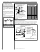
INSTALLATION INSTRUCTIONS MLDVTCD Direct-Vent Contemporary Design Gas Fireplaces P/N 506015-03 Rev. F 06/2011 ™ MODELS This manual is part of a set of three supporting this product. Refer to manual 506017-02 for Care and Operation information and 506019-40 for Facade Installation Instructions. Ce manuel est disponible en francais, simplement en faire la demande. Numéro de la pièce 506223-05. INSTALLER: Leave this manual with the appliance. CONSUMER: Retain this manual for future reference.
LENNOX HEARTH PRODUCTS • MERIT® SERIES DIRECT-VENT CONTEMPORARY DESIGN GAS FIREPLACES • MODEL MLDVTCD-35 • INSTALLATION INSTRUCTIONS PACKAGING TABLE OF CONTENTS Packaging..........................................Page Introduction.......................................Page General Information...........................Page Requirements for the Commonwealth of Massachusetts..Page New York City Approval......................Page Cold Climate Insulation......................
LENNOX HEARTH PRODUCTS • MERIT® SERIES DIRECT-VENT CONTEMPORARY DESIGN GAS FIREPLACES • MODEL MLDVTCD-35 • INSTALLATION INSTRUCTIONS WARNING Improper installation, adjustment, alteration, service or maintenance can cause injury or property damage. Refer to this manual. For assistance or additional information consult a qualified installer, service agency or the gas supplier.
LENNOX HEARTH PRODUCTS • MERIT® SERIES DIRECT-VENT CONTEMPORARY DESIGN GAS FIREPLACES • MODEL MLDVTCD-35 • INSTALLATION INSTRUCTIONS Manifold Gas Supply Pressure (all models) Fuel # Low High Natural Gas (Lo) 2.2" WC (0.55 kPa) (Hi) 3.5" WC (0.87 kPa) Propane (Lo) 6.3" WC (1.57 kPa) (Hi) 10.0" WC (2.49 kPa) Table 3 Test gauge connections are provided on the front of the millivolt and electronic gas control valve (identified IN for the inlet and OUT for the manifold side).
LENNOX HEARTH PRODUCTS • MERIT® SERIES DIRECT-VENT CONTEMPORARY DESIGN GAS FIREPLACES • MODEL MLDVTCD-35 • INSTALLATION INSTRUCTIONS APPLICATION TOP VENT TOP VENT APPLICATION Note: When the unit is installed with one side flush with a wall, the wall on the other side of the unit must not extend beyond the front edge of the unit.
LENNOX HEARTH PRODUCTS • MERIT® SERIES DIRECT-VENT CONTEMPORARY DESIGN GAS FIREPLACES • MODEL MLDVTCD-35 • INSTALLATION INSTRUCTIONS Vent Termination Clearances These instructions should be used as a guideline and do not supersede local codes in any way. Install venting according to local codes, these instructions, the current National Fuel Gas Code (ANSI-Z223.1) in the USA or the current standards of CAN/CSA-B149.1 in Canada.
LENNOX HEARTH PRODUCTS • MERIT® SERIES DIRECT-VENT CONTEMPORARY DESIGN GAS FIREPLACES • MODEL MLDVTCD-35 • INSTALLATION INSTRUCTIONS Exterior HORIZONTAL Vent TERMINATION Clearance Requirements NOTE: Local Codes Or Regulations May Require Different Clearances. * See Item D in the Text Below. P N NOTE: Location Of The Vent Termination Must Not Interfere With Access To The Electrical Service.
LENNOX HEARTH PRODUCTS • MERIT® SERIES DIRECT-VENT CONTEMPORARY DESIGN GAS FIREPLACES • MODEL MLDVTCD-35 • INSTALLATION INSTRUCTIONS MINIMUM CLEARANCES TO COMBUSTIBLES Appliance And Vent Clearances The appliance is approved with zero clearance to combustible materials on all sides (as detailed in Table 5), with the following exception: When the unit is installed with one side flush with a wall, the wall on the other side of the unit must not extend beyond the front edge of the unit.
LENNOX HEARTH PRODUCTS • MERIT® SERIES DIRECT-VENT CONTEMPORARY DESIGN GAS FIREPLACES • MODEL MLDVTCD-35 • INSTALLATION INSTRUCTIONS WARNING Failure to position the parts in accordance with these diagrams or failure to use only parts specifically approved with this appliance may result in property damage or personal injury.
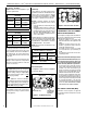
LENNOX HEARTH PRODUCTS • MERIT® SERIES DIRECT-VENT CONTEMPORARY DESIGN GAS FIREPLACES • MODEL MLDVTCD-35 • INSTALLATION INSTRUCTIONS FIREPLACE AND FRAMING SPECIFICATIONS Framing MLDVTCD-35 10-1/2 (267) VENT FRAMING TOP VENT WITH ONE 90° ELBOW Framing Dimensions Model No. Framing should be constructed of 2x4 or larger lumber Inches (mm) A B C D in.
LENNOX HEARTH PRODUCTS • MERIT® SERIES DIRECT-VENT CONTEMPORARY DESIGN GAS FIREPLACES • MODEL MLDVTCD-35 • INSTALLATION INSTRUCTIONS fireplace FRAMING specifications Model No. MLDVTCD-35 A B in. 35 1/4 57 1/2 mm 895 1461 C D 40 5/8 1032 E E 28 3/4 13 3/4 730 349 7 (178) C D A B Back wall of chase/enclosure (including any finishing materials) Inches (millimeters) Figure 12 - Corner Framing with Horizontal Termination Step 2.
LENNOX HEARTH PRODUCTS • MERIT® SERIES DIRECT-VENT CONTEMPORARY DESIGN GAS FIREPLACES • MODEL MLDVTCD-35 • INSTALLATION INSTRUCTIONS Step 3. Install the Vent System Installation of Vent Restrictor General Information A vent restrictor may be needed with this appliance. The restrictor is installed in the appliance top flue outlet as shown in Figure 14, either before adding vent, from above, or after installation of vent from below, within the firebox.
LENNOX HEARTH PRODUCTS • MERIT® SERIES DIRECT-VENT CONTEMPORARY DESIGN GAS FIREPLACES • MODEL MLDVTCD-35 • INSTALLATION INSTRUCTIONS Vertical Termination Systems (Roof) See Figure 15 on Page 13 and Figures 2325 on Pages 16 and 17 and their associated Vertical Vent Tables which illustrate the various vertical venting configurations that are possible for use with these appliances. Secure Vent™ pipe applications are shown in these Figures; Secure Flex™ pipe may also be used.
LENNOX HEARTH PRODUCTS • MERIT® SERIES DIRECT-VENT CONTEMPORARY DESIGN GAS FIREPLACES • MODEL MLDVTCD-35 • INSTALLATION INSTRUCTIONS Vertical (Offset) Installation Analyze the vent routing and determine the quantities of vent sections and number of elbows required. Refer to Vertical Vent Figures and Tables on Pages 16 and 17 to select the type of vertical installation desired.
LENNOX HEARTH PRODUCTS • MERIT® SERIES DIRECT-VENT CONTEMPORARY DESIGN GAS FIREPLACES • MODEL MLDVTCD-35 • INSTALLATION INSTRUCTIONS One method of support is by utilizing field provided support straps (conventional plumber's tape). Secure the plumber's tape to the framing members with nails or screws. Loop the tape around the vent, securing the ends of the tape to the framing. If desired, sheet metal screws #6 x 1/2" length may be used to secure the support straps to the vent pipe.
LENNOX HEARTH PRODUCTS • MERIT® SERIES DIRECT-VENT CONTEMPORARY DESIGN GAS FIREPLACES • MODEL MLDVTCD-35 • INSTALLATION INSTRUCTIONS VERTICAL VENT FIGURES/TABLES Table A Notes: • Secure Vent™ (rigid vent pipe) is shown in the Figures; Secure Flex™ (flexible vent pipe) may also be used.
LENNOX HEARTH PRODUCTS • MERIT® SERIES DIRECT-VENT CONTEMPORARY DESIGN GAS FIREPLACES • MODEL MLDVTCD-35 • INSTALLATION INSTRUCTIONS VERTICAL VENT FIGURES/TABLES (CONTINUED) Table B V Minimum H + H1 Maximum feet (meter) feet (meter) 5 (1.524) 5 (1.524) 1 (0.305) 10 (3.048) 2 (0.610) 15 (4.572) 3 (0.914) 20 (6.096) 4 (1.219) Elbow Only H + H1 = 20 feet (6.096 m) Max. V + V1 + H + H1 = 40 ft. (12.2 m) Max.
LENNOX HEARTH PRODUCTS • MERIT® SERIES DIRECT-VENT CONTEMPORARY DESIGN GAS FIREPLACES • MODEL MLDVTCD-35 • INSTALLATION INSTRUCTIONS Building Support Framing Support Brackets TYPICAL HORIZONTAL VENT INSTALLATION Horizontal / Inclined Run Typical Termination Shown SV4.5E90 Elbow Ceiling SV4.5L6/12/24/36/48 Vent Sections u Firestop / Spacer Vertical Rise SV4.5VF Exterior Wall Support Bracket Spacing Every 5 ft (1.52 m) u When Using Secure Flex, Use Firestop / Spacer SF4.
LENNOX HEARTH PRODUCTS • MERIT® SERIES DIRECT-VENT CONTEMPORARY DESIGN GAS FIREPLACES • MODEL MLDVTCD-35 • INSTALLATION INSTRUCTIONS J. Assemble vent run to exterior wall - If not previously measured, locate the center of the vent at the exterior wall. Prepare an opening as described in Step B. Assemble the vent system to point where the terminus of the last section is located relative to the exterior surface to which the termination is to be attached as shown in Figure 28 and Table 8.
LENNOX HEARTH PRODUCTS • MERIT® SERIES DIRECT-VENT CONTEMPORARY DESIGN GAS FIREPLACES • MODEL MLDVTCD-35 • INSTALLATION INSTRUCTIONS Use Table 8 as an aid in venting component selection for a particular range of exterior wall thicknesses. Table C H Maximum Venting Components Required for Various Exterior Wall Thicknesses, when using Typical Termination Kits Vent Components Required Termination Kit Only Exterior Wall Thickness - inches (mm) 6 to 9-1/4 (152 to 235) Termination Kit and 6 In.
LENNOX HEARTH PRODUCTS • MERIT® SERIES DIRECT-VENT CONTEMPORARY DESIGN GAS FIREPLACES • MODEL MLDVTCD-35 • INSTALLATION INSTRUCTIONS HORIZONTAL VENT FIGURES / TABLES (CONTINUED) Wall Firestop/Spacer Table E (SV4.5HF) H + H1 Maximum H H1 V Note - When using Secure FlexTM, use Firestop/Spacer SF4.5VF. When using Secure Flex, Wall Firestop/Spacer (SV4.5HF) use Firestop/Spacer SF4.5HF. V Minimum feet (meter) feet (meter) 3 (0.914) 5 (1.524) 1 (0.305) 10 (3.048) 2 (0.
LENNOX HEARTH PRODUCTS • MERIT® SERIES DIRECT-VENT CONTEMPORARY DESIGN GAS FIREPLACES • MODEL MLDVTCD-35 • INSTALLATION INSTRUCTIONS HORIZONTAL VENT FIGURES / TABLES (CONTINUED) Table F Typical termination shown. use Firestop/Spacer SF4.5VF. When using Secure Flex, use Firestop/Spacer SF4.5HF. H1 Ceiling Firestop/Spacer (SV4.5VF) (SV4.5HF) V1 V See Table 8 on Page 20 as an aid in venting component selection for a particular range of exterior wall thicknesses. (meter) 5 (1.
LENNOX HEARTH PRODUCTS • MERIT® SERIES DIRECT-VENT CONTEMPORARY DESIGN GAS FIREPLACES • MODEL MLDVTCD-35 • INSTALLATION INSTRUCTIONS Vertical or Horizontal Venting Using Secure Flex™ Kits and Components Secure Flex™ venting kits and components may be used in any venting application in place of rigid Secure Vent™ (SV4.5) direct-vent components. All restrictions, clearances and allowances that pertain to the rigid piping apply to the flexible venting.
LENNOX HEARTH PRODUCTS • MERIT® SERIES DIRECT-VENT CONTEMPORARY DESIGN GAS FIREPLACES • MODEL MLDVTCD-35 • INSTALLATION INSTRUCTIONS Step 4. Field Wiring CAUTION Ground supply lead must be connected to the wire attached to the green ground screw located on the outlet box. See Figure 37. Failure to do so will result in a potential safety hazard.
LENNOX HEARTH PRODUCTS • MERIT® SERIES DIRECT-VENT CONTEMPORARY DESIGN GAS FIREPLACES • MODEL MLDVTCD-35 • INSTALLATION INSTRUCTIONS Ground - Green Neutral - White 120 VAC - Black BLOWER CONTROL CIRCUIT WIRING 120V, 60HZ, 1PH * Wall-mounted ON/ OFF Blower Switch or Variable Speed Control Switch. Junction Box White Tab Broken Black Blower Access Hot Side of Receptacle Red An electrical outlet box is provided for the installation of the FBK-100 and FBK-200 forced air blower kit.
LENNOX HEARTH PRODUCTS • MERIT® SERIES DIRECT-VENT CONTEMPORARY DESIGN GAS FIREPLACES • MODEL MLDVTCD-35 • INSTALLATION INSTRUCTIONS Step 6. Connecting Gas Line Gas Flex Line Connector All codes require a shut-off valve mounted in the supply line. The orientation of the shut-off valve should face the front. Figure 38 illustrates two methods for connecting the gas supply. A Sediment Trap is recommended to prevent moisture and debris in gas line from damaging the valve.
LENNOX HEARTH PRODUCTS • MERIT® SERIES DIRECT-VENT CONTEMPORARY DESIGN GAS FIREPLACES • MODEL MLDVTCD-35 • INSTALLATION INSTRUCTIONS TEST ALL CONNECTIONS FOR GAS LEAKS (FACTORY AND FIELD): WARNING Never use an open flame to check for leaks. Turn on gas supply and test for gas leaks, using a gas leak test solution (also referred to as bubble leak solution).
LENNOX HEARTH PRODUCTS • MERIT® SERIES DIRECT-VENT CONTEMPORARY DESIGN GAS FIREPLACES • MODEL MLDVTCD-35 • INSTALLATION INSTRUCTIONS Step 8. Installing Contemporary Media NOTE: Turn off all electricity to the appliance before you install contemporary floor media. WARNING • DO NOT attempt to install the contemporary media until the appliance installation has been completed, the gas line connected and tested for leaks and the initial burner operation has been checked out.
LENNOX HEARTH PRODUCTS • MERIT® SERIES DIRECT-VENT CONTEMPORARY DESIGN GAS FIREPLACES • MODEL MLDVTCD-35 • INSTALLATION INSTRUCTIONS MLDVTCD-35 Refractory Panels and Contemporary Media Placement Rear Zen Garden Panel Burner Outlet Tumbled River Stone Burner Outlet Black Obsidian Contemporary Glass (Note: River Stone And Beach Sand May Be Used Together) Detail A Detail C Right Zen Garden Panel Left Zen Garden Panel Burner Outlet Contemporary Beach Sand Diamond White Contemporary Glass Burn
LENNOX HEARTH PRODUCTS • MERIT® SERIES DIRECT-VENT CONTEMPORARY DESIGN GAS FIREPLACES • MODEL MLDVTCD-35 • INSTALLATION INSTRUCTIONS Step 9. INSTALLATION AND REMOVAL OF GLASS DOOR WARNING • Do not attempt to substitute the materials used on these doors, or replace cracked or broken glass. • Handle this glass with extreme care! Glass is susceptible to damage – Do not scratch or handle roughly while reinstalling the glass door frame.
LENNOX HEARTH PRODUCTS • MERIT® SERIES DIRECT-VENT CONTEMPORARY DESIGN GAS FIREPLACES • MODEL MLDVTCD-35 • INSTALLATION INSTRUCTIONS Burner Air Shutter Adjustment Procedure Adjustment Set-Screw WARNINGS • Air shutter adjustment should only be performed by a qualified professional service technician. • Ensure front glass panel are in place and sealed during adjustment. Adjustment Rod Up (closed min.
LENNOX HEARTH PRODUCTS • MERIT® SERIES DIRECT-VENT CONTEMPORARY DESIGN GAS FIREPLACES • MODEL MLDVTCD-35 • INSTALLATION INSTRUCTIONS Step 11. Hood Installation Finishing Requirements - Contemporary Facade (Refer to Figure 47) All of these appliances must have hoods installed prior to operating. This contemporary unit is uniquely suited for mid-wall installations with an available self-finishing decorative contemporary Facade.
LENNOX HEARTH PRODUCTS • MERIT® SERIES DIRECT-VENT CONTEMPORARY DESIGN GAS FIREPLACES • MODEL MLDVTCD-35 • INSTALLATION INSTRUCTIONS Step 12. ATTACHING SAFETY-IN-OPERATION WARNINGS It is the installers responsibility to ensure these warnings are properly affixed during installation. These warning labels are a critical step in informing consumers of safe operation of this appliance.
LENNOX HEARTH PRODUCTS • MERIT® SERIES DIRECT-VENT CONTEMPORARY DESIGN GAS FIREPLACES • MODEL MLDVTCD-35 • INSTALLATION INSTRUCTIONS Installation Accessories Cat.No. H1968 94L10 SV4.5HTSS Horizontal Termination Small Square with Firestop/Spacer (H2246) and Adapter (74L61) H5817 SV4.5-20SS- Small Square Termination, WSK 20" With Shield H2152 SV4.5CGV-1 Vertical Termination (High Wind) 77L70 77L71 77L72 77L73 77L74 77L75 77L76 77L77 34 Listed Secure Vent™ Components Model No. Description SV4.
Listed Secure Flex™ Components LENNOX HEARTH PRODUCTS • MERIT® SERIES DIRECT-VENT CONTEMPORARY DESIGN GAS FIREPLACES • MODEL Cat. MLDVTCD-35 • INSTALLATION INSTRUCTIONS No. H1988 Listed Secure Flex™ Components Cat. Model No. Description No. These termination kits include firestop/spacer, gear clamps and flex adapter. H1969 SF4.
LENNOX HEARTH PRODUCTS • MERIT® SERIES DIRECT-VENT CONTEMPORARY DESIGN GAS FIREPLACES • MODEL MLDVTCD-35 • INSTALLATION INSTRUCTIONS Gas Conversion Kits Installation Instructions WARNING This conversion kit shall be installed by a qualified service agency in accordance with the manufacturer’s instructions and all applicable codes and requirements of the authority having jurisdiction.
LENNOX HEARTH PRODUCTS • MERIT® SERIES DIRECT-VENT CONTEMPORARY DESIGN GAS FIREPLACES • MODEL MLDVTCD-35 • INSTALLATION INSTRUCTIONS Millivolt Appliances Electronic Appliances All Models Step 5. SIT Systems - Refer to Figure 50 on Page 37 and the instructions provided with the kit. Using a Torx T20 (with 1/4" shank and center hole), tool or standard flat screwdriver remove and discard the three pressure regulator mounting screws.
LENNOX HEARTH PRODUCTS • MERIT® SERIES DIRECT-VENT CONTEMPORARY DESIGN GAS FIREPLACES • MODEL MLDVTCD-35 • INSTALLATION INSTRUCTIONS Lennox Hearth Products reserves the right to make changes at any time, without notice, in design, materials, specifications, prices and also to discontinue colors, styles and products. Consult your local distributor for fireplace code information. Printed in U.S.A. © 2009 Lennox Hearth Products P/N 506015-03 Rev.