
user manual


Page 4
For installation on combustible material.
WARNING
Product contains fiberglass wool.
Disturbing the insulation in this product during
installation, maintenance, or repair will expose you
to fiberglass wool dust. Breathing this may cause
lung cancer. (Fiberglass wool is known to the State
of California to cause cancer.)
Fiberglass wool may also cause respiratory, skin,
and eye irritation.
To reduce exposure to this substance or for further
information, consult material safety data sheets
available from address shown below, or contact your
supervisor.
Lennox Industries Inc.
P.O. Box 799900
Dallas, TX 75379−9900
Location Selection
Use the following guidelines to select a suitable location for
these units.
1 − Unit is designed for outdoor installation only. Unit must
be installed so all electrical components are protected
from water.
2 − Condenser coils must have an unlimited supply of air.
3 − For ground level installation, use a level pre−fabricated
pad or use a level concrete slab with a minimum thick-
ness of 4 inches. The length and width should be at
least 6 inches greater than the unit base. Do not tie the
slab to the building foundation.
4 − Maintain level within a tolerance of 1/4 inch maximum
across the entire length or width of the unit.
Rigging & Setting Unit
Exercise care when moving the unit. Do not remove any
packaging until the unit is near the place of installation. An
optional lifting lug kit (92M51) may be purchased
separately for use in rigging the unit for lifting. Spreaders
MUST be used across the top of the unit. Recommended
spreader length: 2, 2−1/2, 3−ton units −− 44"; 3−1/2, 4, 5−ton
units −− 54".
CAUTION
Before lifting a unit, make sure that the weight is dis-
tributed equally on the cables so that it will lift even-
ly.
Units may also be moved or lifted with a forklift while still in
the factory supplied packaging.
NOTE − Length of forks must be a minimum of 42 inches.
Figure 1
Accessory Lift Kit
Lifting Bracket
Accessory
Sheet Metal
Screw
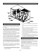
Clearances
All units require certain clearances for proper operation
and service. Refer to figure 2 for the clearances required
for combustible construction, servicing, and proper unit
operation.
Figure 2
Service Clearances
3 (156)*
48 (1219)
30
(762)
24
(610)
*Rear clearance is 18" (457) when required for
accessory maintenance.
NOTE − Top Clearance − 36 in. (914 mm)
NOTE − Entire perimeter of unit base requires
support when elevated above mounting surface.
FRONT
REAR
NOTE − Do not permit overhanging structures or shrubs to
obstruct condenser air discharge outlet.
In the U.S. units may be installed on combustible floors
made from wood or class A, B, or C roof covering material.
In Canada, units may be installed on combustible floors.