
user manual


Page 5
Existing Common Vent Systems
The 15CHAX packaged cooling units with auxiliary electric
heat may replace an existing furnace which is being re-
moved from a venting system commonly run with separate
gas appliances. In this case, the existing vent system is
likely to be too large to properly vent the remaining at-
tached appliances.
Conduct the following test while each appliance is operat-
ing and the other appliances (which are not operating) re-
main connected to the common venting system. If the vent-
ing system has been installed improperly, you must
correct the system as indicated in the general venting re-
quirements section.
1 − Seal any unused openings in the common venting sys-
tem.
2 − Inspect the venting system for proper size and horizon-
tal pitch. Determine that there is no blockage, restric-
tion, leakage, corrosion, or other deficiencies which
could cause an unsafe condition.
3 − Close all building doors and windows and all doors be-
tween the space in which the appliances remaining
connected to the common venting system are located
and other spaces of the building. Turn on clothes dry-
ers and any appliances not connected to the common
venting system. Turn on any exhaust fans, such as
range hoods and bathroom exhausts, so they will oper-
ate at maximum speed. Do not operate a summer ex-
haust fan. Close fireplace dampers.
4 − Follow the lighting instructions. Turn on the appliance
that is being inspected. Adjust the thermostat so that
the appliance operates continuously.
5 − After the main burner has operated for 5 minutes, test
for leaks of flue gases at the draft hood relief opening.
Use the flame of a match or candle, or smoke from a
cigarette, cigar, or pipe.
6 − After determining that each appliance connected to the
common venting system is venting properly, (step 3)
return all doors, windows, exhaust fans, fireplace
dampers, and any other gas−burning appliances to
their previous mode of operation.
7 − If a venting problem is found during any of the preced-
ing tests, the common venting system must be modi-
fied to correct the problem.
Resize the common venting system to the minimum
vent pipe size determined by using the appropriate
tables in Appendix G. (These are in the current stan-
dards of the National Fuel Gas Code
ANSI-Z223.1/NFPA 54 in the USA, and the appropri-
ate Category 1 Natural Gas and Propane appliances
venting sizing tables in the current standards of the
CSA B149 Natural Gas and Propane Installation
Codes in Canada.)
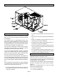
Condensate Drain
The 15CHAX unit is equipped with a 3/4 inch FPT coupling
for condensate line connection. Plumbing must conform to
local codes. Use a sealing compound on male pipe
threads.
The drain line must be properly trapped and routed to a
suitable drain. See figure 3 for proper drain arrangement.
The drain line must pitch to an open drain or pump a
minimum of 1 inch per 10 feet to prevent clogging of the
line. Seal around drain connection with suitable material to
prevent air leakage into return air system.
NOTE − Drain line connection may not carry the weight of
the unsupported drain line. Support the drain line, if
necessary.
Drain piping should not be smaller than drain connection at
coil. An open vent in drain line will some times be required
due to line length, friction and static pressure. Drains
should be constructed in a manner to facilitate future clean-
ing.
NOTE − The condensate drain line MUST be trapped to
provide proper drainage.
CAUTION
Condensate line connection must be hand−tight-
ened. Do not use tools.
Figure 3
Typical Condensate Drain
Unit
Drain Connection
Positive Liquid Seal Required
3.00” Min.
1.00” Min.
12.00”
Max.