
user manual


Page 7
Unit must be electrically grounded in accordance with local
codes or in the absence of local codes with the National
Electric Code, ANSI/NFPA No. 70 (latest edition) or CSA
C22.2 Part 1 (latest edition).
Power supply to the unit must comply with all applicable
codes and NEC or CEC. A fused disconnect switch should
be field provided for the unit. The switch must be separate
from all other circuits. If any of the wire supplied with the
unit must be replaced, replacement wire must be of the
type shown on the wiring diagram.
Electrical wiring must be sized to carry minimum circuit
ampacity marked on the unit. USE COPPER
CONDUCTORS ONLY. Each unit must be wired with a
separate branch circuit and be properly fused.
WARNING
Unit is equipped with a single−pole contactor. Line
voltage is present at all components when unit is not
in operation. Disconnect all remote electric power
supplies before opening access panel. Unit may
have multiple power supplies. Failure to disconnect
all power supplies could result in personal injury or
death.
CAUTION
When connecting electrical power and control wir-
ing to the unit, waterproof type connectors MUST be
used so that water or moisture cannot be drawn into
the unit during normal operation.
WARNING
Unit must be grounded in accordance with national
and local codes. Failure to ground unit properly can
result in personal injury or death.
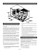
See figure 6 for typical field wiring connections and figure 7
for typical unit wiring diagram.
Optional Electric Heat
Optional electric heat is available and must be purchased
separately. Install the electric heat section as outlined in
the installation instructions packaged with the electric heat
section.
Thermostat
The room thermostat should be located on an inside wall
where it will not be subject to drafts, sun exposure or heat
from electrical fixtures or appliances. Follow
manufacturer’s instructions enclosed with thermostat for
general installation procedure. Color coded insulated wires
(# 18 AWG) should be used to connect thermostat to unit.
Typical Single−Phase Unit Wiring Connections
Figure 6