
Water Heater User Manual


Page 3
CBWMV SERIES
General
These instructions are intended as a general guide and do
not supersede local codes in any way. Consult authorities
having jurisdiction before installation. Only qualified ser-
vice technicians or installers may install and service this
unit.
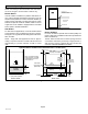
CBWMV Unit Parts Arrangement
CBWMV Unit
HOT WATER
COPPER
TUBE COIL
CBWMV
CONTROL BOX
SUPPLY AIR
BLOWER
INSULATED
STEEL
CABINET
Figure 1
CBWMV Unit Parts Description
Blower
The CBWMV is equipped with a variable speed motor that
provides separate cooling and heating CFM selections
and low continuous fan speeds.
Hot Water Coil
The copper tube coil is equipped with aluminum fins which
provide excellent heat transfer. Manual air bleed ports are
located in the copper tubing to release trapped air in the
water circuit in all unit configurations.
Blower Control
The control provides a fixed blower delay of 45 seconds
ON / 30 seconds OFF on a W call.
Thermostat and accessory connections are made to the
terminal strips in the control box.
CBWMV Unit Optional Accessories
Accessory Circulators (53J76, 99K69)
An accessory circulator should be used in long line ap-
plications. Two circulators are available with either 9 gal-
lons per minute (99K69) or 14 gpm (53J76) flow rate. Both
units have 7/8" soldering joints (inlet and outlet) . See pip-
ing section for more information.
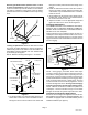
Downflow Base (68M03)
A downflow base kit is available for downflow applications
without add−on cooling coils. The base provides clearance
for routing the CBWMV unit’s inlet and outlet water lines.
NOTE − Downflow applications with an add−on cooling coil
require field−fabricated transitions to provide adequate
clearance for servicing/removing the cooling coil without
cutting the water lines.