
Air Conditioner User Manual

Page 3
XC21 SERIES
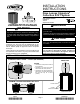
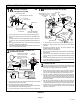
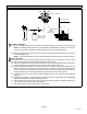
INSTALL UNIT AWAY
FROM WINDOWS
TWO 90_ ELBOWS INSTALLED IN LINE SET
WILL REDUCE LINE SET VIBRATION
PLACEMENT
FIGURE 2
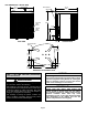
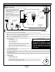
Install unit level or, if on a slope, maintain slope tolerance of 2
degrees (or 2 inches per 5 feet [50 mm per 1.5 m]) away from
building structure.
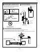
GROUND LEVEL
MOUNTING
SLAB
BUILDING
STRUCTURE
DISCHARGE AIR
SLAB MOUNTING
FIGURE 3
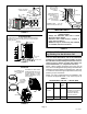
LEG DETAIL
BASE
2" (50.8MM) SCH 40
FEMALE THREADED
ADAPTER
ELEVATED SLAB MOUNTING USING FEET
EXTENDERS
2" (50.8MM)
SCH 40 MALE
THREADED
ADAPTER
Use additional 2" SCH 40 male
threaded adapters which can
be threaded into the female
threaded adapters to make
additional adjustments to the
level of the unit.
FIGURE 4
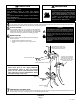
Unit Stabilizer Bracket Use
(field−provided):
Always use stabilizers when unit is raised
above the factory height.
(Elevated units could become unstable in
gusty wind conditions.)
Stabilizers may be used on any unit installed
on unstable and uneven surfaces.
Concrete slab use two
plastic anchors (hole drill 1/4")
COIL
BASE PAN
CORNER POST
STABILIZING BRACKET
(18 GAUGE METAL 2"
WIDTH; HEIGHT AS
REQUIRED)
#10 X 1/2" LONG
SELF−DRILLING
SHEET METAL
SCREWS
#10 X 1−1/4" LONG
HEX HD SCREW AND
FLAT WASHER
STABILIZING UNIT ON UNEVEN SURFACES
!
IMPORTANT !
FIGURE 5
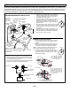
STEP 2 −− REFRIGERANT PIPING −− Flush-
ing Existing Line Set & Indoor Coil
Flush the existing line set per the following instruc-
tions. For more information, refer to the Installation
and Service Procedures manual available on Dave-
Net. CAUTION − DO NOT attempt to flush and re−use ex-
isting line sets or indoor coil when the system con-
tains contaminants (i.e., compressor burn out).
NOTE − When installing refrigerant lines longer than 50
feet, refer to the Refrigerant Piping Design and Fabrication
Guidelines manual available on DaveNet (Corp. 9351−L9),
or contact the Technical Support Department Product Ap-
plication group for assistance.
NOTE − For new or replacement line set installation, refer
to Service and Application Note − Corp. 9112−L4 (C−91−4).
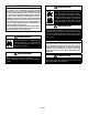
TABLE 1
REFRIGERANT LINE SET INCHES (MM)
Models Liquid
Line
Vapor/
Suction
Line
L15 Line Set
−024, −036
and−048
3/8 (10) 7/8 (22) L15 line set sizes are
dependent on unit match up.
See XP21 Engineering
Handbook to determine
correct line set sizes.
−060 3/8 (10) 1−1/8 (29) Field Fabricated
NOTE Some applications may required a field−provided 7/8" to
1−1/8" adapter.